Have you ever wondered why some mechanical components run smoothly while others cause vibrations and premature wear?
Often, the key lies in correct geometric dimensioning and tolerancing, including size tolerance especially in total runout control.
A recent industry study by Google shows that manufacturing companies with adequate concentricity controls experience up to 37% fewer part failures and warranty claims.
That’s significant! Whether you are designing gear shafts or complex gears, knowing the overall runout can make or break the effectiveness of your component.
This article explains total runout, how it’s measured and why it’s so important in precision manufacturing.
What is Total Runout?
Total runout (gd&t) measures how much the entire surface of a part changes when it is rotated around a reference axis.
Unlike other checks that look at specific cross-sections, total runout looks at the entire cylindrical surface at the same time. Think of this as the maximum deviation of each surface element from its theoretically ideal position.
Overall concentricity is crucial when working with rotating components such as pump parts or gear shafts, especially in relation to the datum surface . It combines two important elements: the straightness of your component and the consistency of its surface.
Many people confuse it with runout, but there is an important difference: total runout evaluates the entire surface of the part at once, while runout checks specific cross-sections.
The total runout symbol resembles a filled triangle with two arrows pointing in opposite directions. When you see this symbol on a drawing, it means that you are working with a part that requires precise control of its overall shape.
GD&T Symbols Related to Total Runout
1. Total Runout Symbol
You must first identify this main symbol. It consists of a continuous triangle between two arrows pointing in opposite directions. If you see this symbol on a drawing, it means that the entire surface must be controlled in relation to a reference axis.
The total runout symbol is displayed in the control frame of the feature together with the tolerance value and the reference points, which also may include circular runout controls . This symbol indicates to manufacturing that they need to check the entire surface of the part, not just specific cross sections.
2. Circular Runout Symbol
This symbol is similar to the total runout symbol, but only has an arrow. Although it is not a specific symbol for total runout, knowing the difference is absolutely critical. Runout measures how far the individual cross sections of your component deviate from perfect circles.
You may see both symbols on the same drawing if your parts have multiple cylindrical features. Typically, the runout symbol requires less stringent manufacturing techniques than overall runout.
3. Diameter Symbol
The diameter symbol (\u00d8) is usually found on runout indicators and shows that a cylindrical feature has total runout. When checking drawings, this symbol is displayed before the runout check measurements.
Runout checks and the diameter symbol work together to ensure that your cylindrical components maintain the correct shape. This combination prevents problems such as vibrations in rotating machine components.
4. Feature Control Frame
All geometric tolerance data — including the total runout symbol, tolerance value and datums — is located in this rectangular box. When reading plans, it is clear how the total runout should be measured and what limits apply when the Feature control frame is used.
A typical feature control frame for total runout might show the symbol, a tolerance value such as 0.05mm and primary and secondary datums.
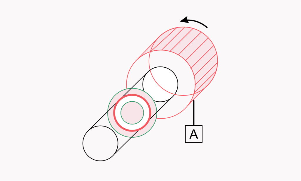
Total Runout Tolerance Zone
The permissible deviation of the entire surface of your part is defined by the total runout tolerance zone. Unlike other tolerances, which can emphasise a single cross-section, the total runout tolerance zone applies to each surface component at once.
Think of it like this: Each surface point must stay within two concentric cylinders as you rotate your component around its reference axis. Your tolerance zone is the space between these two coaxial cylinders. The width of this zone corresponds to the boundary of the feature control frame you specify.
The tolerance zone lies between two parallel planes for flat surfaces that are perpendicular to the axis. When checking complicated components and cylindrical and flat surfaces, each type of surface is given its own suitable zone shape; however, they must all fulfil the same tolerance value.
The tolerance zones for overall concentricity are difficult because they simultaneously control form deviation, alignment and position. This all-encompassing control guarantees that your component not only appears correct in one place, but also functions ideally over its entire surface. The tighter the tolerance field, the more accurate your manufacturing process needs to be.
How to Measure Total Runout
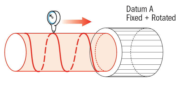
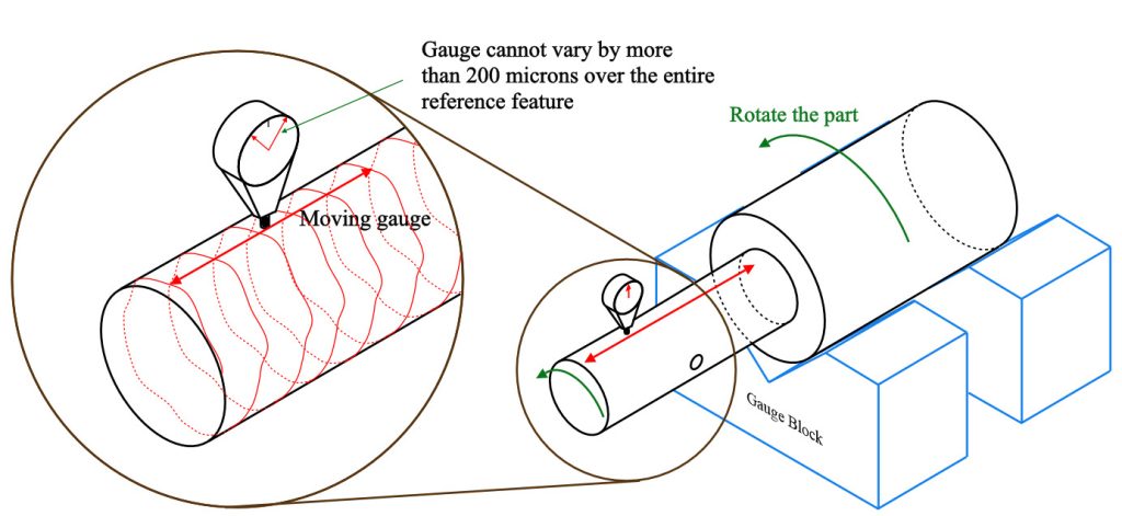
Measuring total runout requires suitable tools and careful preparation. Set the reference axis by first placing your component on two V-blocks or between centres. This configuration ensures that your part can rotate freely around its centre axis while maintaining constant reference points.
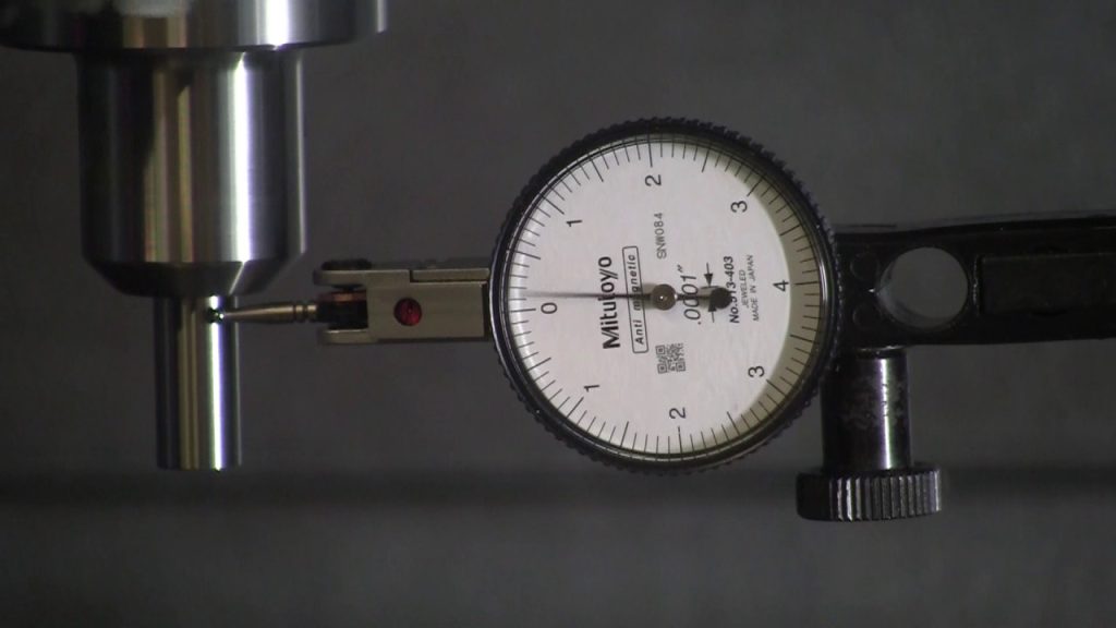
Then place a dial indicator on the surface to be tested. As the component rotates, the dial gauge must touch the entire surface. Unlike circular runout measurement, where individual cross-sections must be checked, this is not necessary.
Observe the dial indicator display as you slowly rotate the component through 360 degrees. The total concentricity displayed is the difference between the maximum and minimum measured value. This shows how much the entire surface deviates from the ideal alignment to the reference axis.
For complicated shapes or large components such as pump shafts, multiple measurements may be required at different locations. For more accurate measurements, some stores use automatic measuring machines or height gauges.
Remember that rotation requires constant surface contact with the measuring tool. Clean your part completely before measuring, as dust, crisps or surface defects could distort your readings. A correct measurement guarantees that your components function as intended and comply with the specified total runout tolerance.
Applications of Total Runout
Rotating machine components
For components such as gear shafts, where even small changes in shape can lead to vibrations. Tight concentricity tolerances guarantee smooth operation at all speeds when designing high-speed rotating components.
To avoid stress concentrations and premature wear, the entire cylindrical surface must remain correctly aligned with the centerline. Without proper control of overall concentricity, these expensive devices could fail long before their expected service life.
Sealing surfaces
For parts that need to be sealed liquid or gas tight, overall concentricity is critical. Think of valve seats or pump housings; these components rely on regular surface contact to prevent leakage. The concentricity tolerance zone guarantees that the entire referenced surface maintains the correct shape in relation to the reference axis.
Small deviations in the entire part can lead to leakage; therefore many fluid handling components require strict overall concentricity tolerances rather than simple dimensional tolerances.
Mounting Alignment
Checking the overall runout ensures the correct alignment of components that must fit with great accuracy. Specifying the total runout in relation to common reference points guarantees correct alignment when multiple cylindrical elements must have a common axis.
Complex assemblies with multiple concentric circles or cylindrical surfaces that need to work together benefit most from this application. Good examples are precision instruments, bearing assemblies and gears.
Automotive components
For key drivetrain components, vehicle manufacturers rely heavily on complete concentricity control. Proper concentricity control helps ensure that parts such as crankshafts, camshafts and brake rotors operate smoothly and avoid vibration.
Maintaining balance during high-speed rotation requires control of the entire surface of the part in relation to its centerline. The next time you have a vibration-free, smooth ride, you can attribute it to controlling overall concentricity!
Frequently Asked Questions on Total Runout
Q: What is total runout in GD&T and how does it differ from runout?
A: While conventional runout only measures individual cross-sections, total runout measures the entire surface simultaneously with respect to a reference axis. Think of total runout as a more thorough test; it examines your entire cylindrical surface at once, rather than slice by slice.
Q:Why is total runout so important for checking cylindrical components?
A: By ensuring that the entire cylindrical surface remains within tolerance, total runout prevents vibration in rotating components. Good concentricity control on your gear shafts or complicated gears will help them run smoother, last longer and generate less noise during operation.
Q:How is total runout measured and what tools are used?
A: You measure total runout with a dial indicator by rotating the component on V-blocks or between centres. While the dial gauge touches the surface, the part rotates around its reference axis. The total runout displayed is the maximum deviation during a complete rotation.
Q:How is the tolerance zone defined and used for total runout?
A: The total runout tolerance is the area between two concentric cylinders around the reference axis. During a rotation, every point on the surface of your part must remain within these two coaxial cylinders. The distance between these cylinders is the tolerance range you specify.
Conclusion
Now you’re equipped with practical knowledge about total runout!
From understanding the total runout symbol to setting up proper measurements, you’ve got the essentials covered. Remember that controlling the entire surface simultaneously is what makes total runout different from other GD&T controls.
Whether you’re designing transmission shafts or checking complex components, applying these concepts will help you create parts that function better and last longer. Next time you see that distinctive total runout symbol on a drawing, you’ll know exactly what it means and why it matters.