Computer Numerical Control (CNC machining) is a cornerstone of modern manufacturing, enabling the production of highly precise metal parts and plastic components from raw material.
This subtractive manufacturing process uses computer-controlled cutting tools to remove material from a solid workpiece, shaping it into the desired shape based on a digital CAD file. It is used in aerospace, automotive, and medical device manufacturing.
This comprehensive CNC machining design guide provides engineers and designers with detailed guidelines to create CNC machined parts that are manufacturable, cost-effective, and meet stringent functional requirements.
Design Guidelines for Common Features
Designing parts for CNC machining requires a deep understanding of the process’s capabilities and limitations. In the following sections, you will learn about the best practices for common features concerning CNC machined parts so that they are functional and manufacturable.
Tolerances
Tolerances limit the permitted amount of dimensional variation for the parts so that the CNC-machined parts fit and function as specified.
For CNC machining, standard tolerances are set at ±0.005 inches (0.127 mm) to ±0.001 inches (0.025 mm), depending on the machine, material, and complexity of a feature.
However, advanced machine shops can maintain tight tolerances down to ±0.0005 inches (0.0127 mm) for features such as reamed holes, but at the cost of slower machining time, specialty tools, and more quality checks, which adds to both production time and CNC machining costs.
The CNC machining design should consider the following:
Selectively Apply Tight Tolerances:
Use tight tolerances on critical dimensions, for example, mating surfaces, or functional interfaces, to keep down CNC machining costs while using looser tolerances for non-critical features to speed the CNC machining process.
Material Considerations:
Thermoplastic materials undergo thermal expansion and contraction. Materials prone to thermal expansion and contraction are better off being kept with tolerances wider than ±0.1 mm (0.004 inches). Materials such as PEEK are a good choice for tight tolerances in plastic machined parts.
Precision and Cost Balance:
If you excessively specify tolerances, you will unnecessarily waste machining time and CNC machining costs. To avoid this, you must consult with manufacturing partners to determine feasible tolerances for your application.
As a designer, you can maintain cost-efficiency and meet functional requirements of CNC machined parts by carefully specifying tolerances in technical drawings.
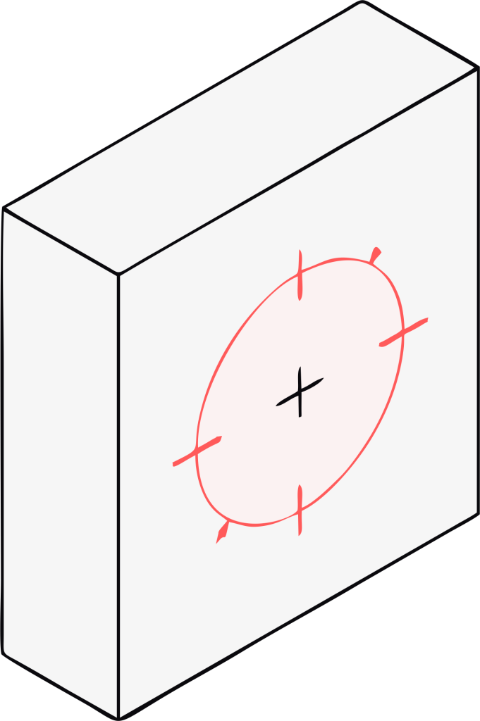
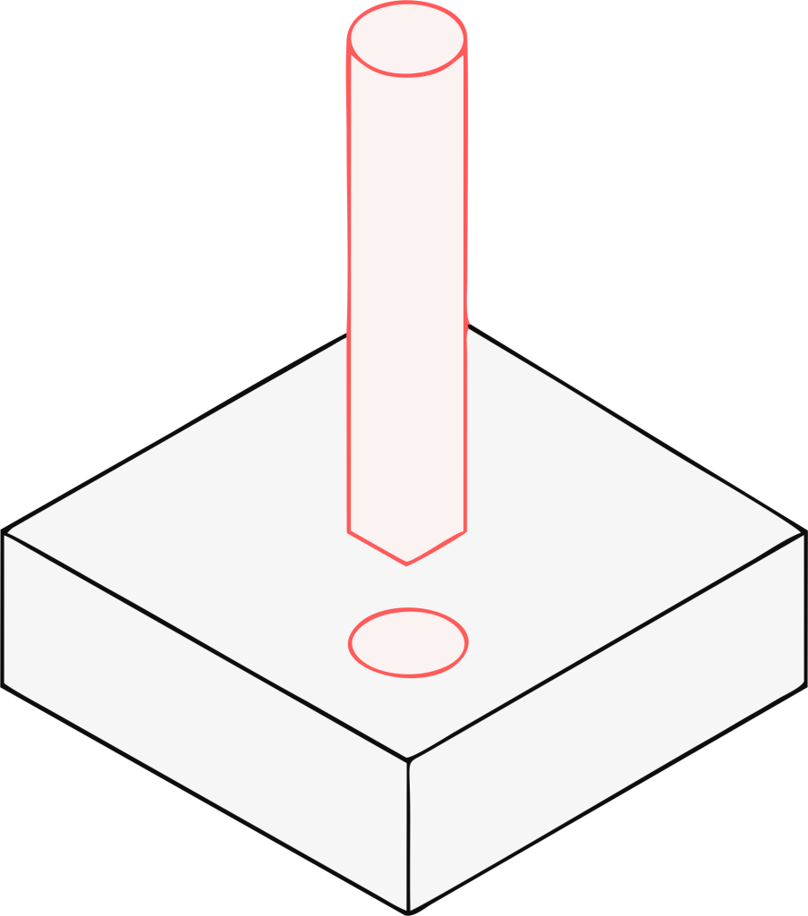
Holes
Holes are essential features in CNC machined parts, serving purposes such as fastening, alignment, or fluid passage.
Through Holes
These holes are called through holes because they pass completely through the part. Due to this, you can efficiently carry out chip evacuation and cooling in the CNC machining process.
A drill bit makes machining of these holes easier. You must use them wherever required because they they reduce the risk of cutting tool damage and easily do reaming or threading.
Blind Holes
Blind holes do not penetrate the part fully and require careful depth specification. To achieve the desired shape, add at least 25% extra depth to account for the conical drill tip, typically angled at 135°.
For example, a 10 mm deep blind hole with a 5 mm drill bit should have a total depth of at least 12.5 mm to ensure the functional maximum depth is met. This additional depth accommodates chip accumulation and the drill bit’s tool geometry.
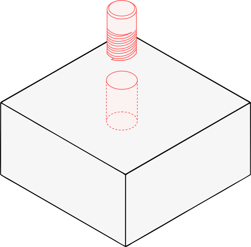
Threaded Holes
Screws and bolts make great use of threaded holes because you need a precise CNC design to ensure strength and manufacturability.
Additionally, you should also use standard hole diameter sizes, such as M6 or larger, so that you dont have to use special tools like custom taps which will increase your CNC machining costs and lead time. Ensure thread engagement of 1.5 to 3 times the hole diameter for sufficient strength.
Proper CNC machining design ensures holes are machinable and meet functional requirements without compromising part integrity.
Drilling Guidelines
The following guidelines for hole design optimization pertain to CNC machining:
Avoid Partial Holes:
Drilled holes should be received fully within the material, so that drill tip wander does not deviate the hole placement from its specified coordinates or cause damage to the cutting tool.
Keep Drill Axis Perpendicular:
The drilling axis should be kept perpendicular to the surface for accuracy and longevity of the cutting tool. Drills performed off-perpendicular to surface level will need special tools or multi-axis machines, increasing the complexity.
Avoid Drilling through Cavities:
Drill paths must be checked not to intersect cavities as their interference would cause cutting tool breakage and adversely affect the hole quality. If cavities cannot be avoided, engage with your manufacturing partners at the earliest to explore alternative machining processes.
Use Standard Drill Sizes:
Drilling holes using standard drill bit sizes, which run from 0.2 mm to 25 mm, helps reduce CNC machining costs and simplify the CNC machining process. Cluster drilled holes with similar hole diameters together as much as possible to reduce cutting tool changes and, consequently, production time.
Avoid Deep Taps:
Limit the tap depth to three times the hole diameter to prevent tear breakage and ensure sufficient thread engagement. Consider deeper threaded holes with thread-forming screws or inserts.
By adhering to these guidelines, designers can create holes that are both functional and cost-effective, minimizing challenges during the CNC machining process.
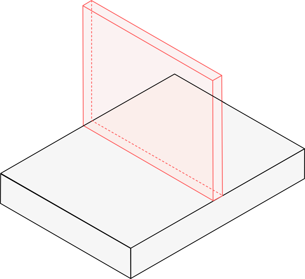
Wall thickness
Thin walls can lead to vibration, tool deflection, and poor surface finish, while overly thick walls increase raw material costs and machining time.
The recommended minimum wall thickness is as follows:
Document
Materials
Recommended Minimum
Feasible Minimum
Metal Parts
0.8 mm (0.031 in)
0.5 mm (0.020 in)
Plastics
1.5 mm (0.059 in)
1.0 mm (0.039 in)
If you want to make the part more stable, you must make sure that wall thickness is uniform and the amount of stress is reduced so that the machining process is more efficient.
For CNC machining parts that have thin walls, it is worth considering the addition of ribs or gussets to improve rigidity without making it heavy.
Additionally, you must gradually shift between thick and thin walls which helps to avoid sharp internal corners and issues with th machining process. Also, when designing tall vertical walls, you must make sure there is no interference and it is dimensionally accurate. To do this, ensure you have tool access.
Threads and Inserts
Threaded holes and inserts are all paramount for fastening in CNC machined parts and involve a precise CNC machining design to acquire strength and manufacturability.
For threaded holes, always use a standard hole diameter size (say, M6 or larger) so you do not require any special tools such as custom taps, as these increase both CNC machining cost and lead time.
Ensure that thread engagement is between 1.5 to 3 times the diameter of the hole to offer sufficient strength; for small threaded holes, provide a clearance section at the bottom so that the tap does not break. The pilot hole diameter must correspond to the chosen tap for perfect threading.
Inserts such as helical or press-fit inserts are placed to improve thread life in soft materials or in applications where wear is high.
Diameter and maximum depth of holes must be in accordance with inserts; these should be on the technical drawing for clarity.
Limit tap depths to three times the diameter of the hole in order to discourage breakage of cutting tools, and involve manufacturing in the selection of appropriate thread standards and insert types.
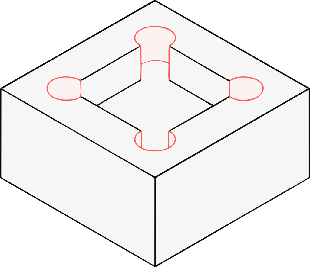
Text
Adding text onto CNC-machined parts for markings or branding purposes is a job that demands proper CNC machining design so that it is clearly legible and can be manufactured with ease.
Engraving is preferred over embossing because it is much easier to machine using a cutting tool, and it also comes out clearer. Sans-serif fonts like Arial are generally preferred with a minimum size of 20-point characters or 5 mm in height for legibility.
Make shallow depth to keep from weakening the part, and the width of the text should be equal to that of the smallest available tool.
Text should be placed on flat surfaces to avoid distortion, and the font should be simplified to lessen the number of machining steps. The smaller the cutting tool, the finer the detail, but this increases machining time.
So the finer the detail selected, the greater the CNC machining cost. CNC machining should specify all text features on the technical drawing to reproduce the text with fidelity during machining.
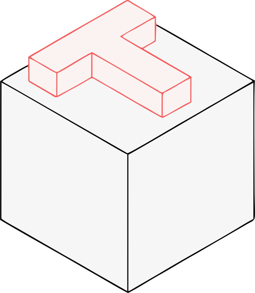
Radii
Corner radius is an essential feature in CNC machining to avoid sharp internal corners that are hard to make due to the cylindrical geometry of cutting tools such as end mill tools and ball end mills.
The internal corner radius should be as big as half the diameter of the tool to be used. Thus if the cutting tool diameter is 1/4 inch, the minimum corner radius must be 1/8 inch (3.18 mm). A corner radius of more than 1/3 of the variable cavity depth is also preferable to provide better tool access and strength to the part.
For exteriors with sharp corners, chamfers should be used instead of sharp edges to provide greater safety and aesthetics.
When the corner radius is consistent throughout the part, less cutting tool changes will be needed, thereby reducing machining time. Having the largest internal radii in your design promotes faster material removal and more efficient CNC machining, benefiting cost and lead time.
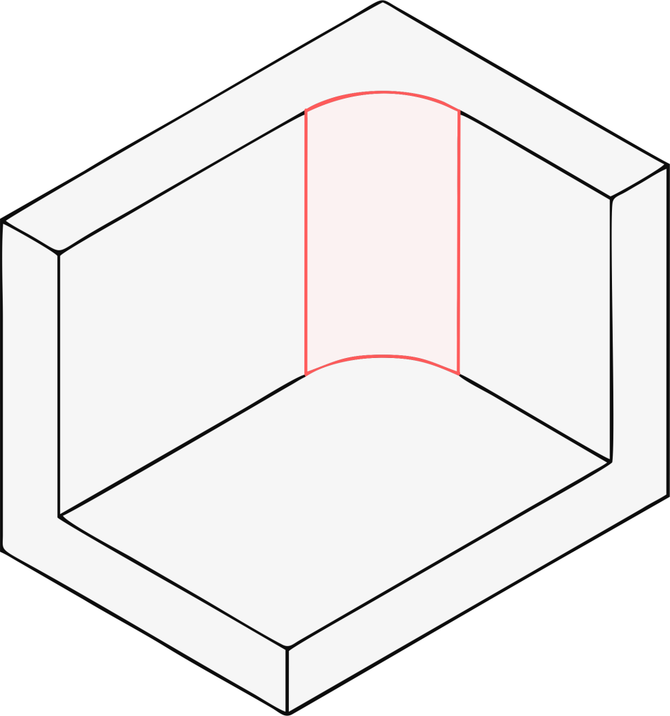
Cavities and Pockets
Cavities and pockets are some deep features that must be CNC machined with consideration of possible interference with the tool and the structural integrity of the part. Generally, the depth-to-width ratio should be limited to 4:1 to avoid sharp internal corners, since they cause tool deflection and a poor surface finish.
Use at least 0.5-mm internal corner radius or 1/3 of the variable cavity depth to assist CNC machining and reduce stress concentrations. The tiny floor corner radius (e.g., 0.5 mm) aids the surface finish and durability of the part.
Consider stepped designs for deeper cavities and pockets to enhance material removal and ensure tool access. T-bone undercuts are used when sharp corners are required, letting a standard tool form the desired shape.
Make sure that variable cavity depth and corner radius are clearly specified on technical drawings for exact CNC machining.
CNC Machining Design Guide For Milling Process
CNC milling involves rotating cutting tools, such as end mill tools, to remove material along a circular path, creating deep features like slots, cavities and pockets, and machine contours.
This machining process is ideal for producing complex geometries but requires careful CNC machining design to optimize efficiency and quality.
Use Standard Cutting Tools
Standard tools, including flat end mill tools and ball end mills, will be cheaper and more readily available, reducing lead time and CNC machining costs. Non-standard or specialty tools may be necessary for peculiar cylindrical geometry or tight tolerances, which results in increased production time.
Aligning feature dimensions to the standard tool diameter simplifies the CNC machining process. For example, a pocket with a corner radius equal to a standard 1/4″ end mill tool will machine much easier than one requiring a special tool.
Avoid Sharp Internal Corners
Sharp internal corners are nearly impossible to machine in CNC milling because of the cylindrical geometry of the cutting tools.
Include an internal corner radius larger than or equal to the tool diameter so there is sufficient clearance for the tool to remove materials and reduce stress concentrations. For example, a 6 mm end mill requires a minimum internal corner radius of 3 mm.
The avoidance of sharp internal corners will also prolong the life of the cutting tool and improve surface finish, and thus the quality of the machined parts.
Avoid Deep, Narrow Slots
Deep features with such narrow slots cause tool deflection and vibrations, generating inaccuracies in dimensions and characteristics contrary to a fine finish; hence, they must be stably designed with minimum width-to-depth ratio of 3:1 for slots.
If deeper slots should be created, stepped designs or other machining processes such as wire EDM are considered with manufacturing partners.
Design with the Largest Possible Internal Radii
Allowing the greatest internal radii possible in milled deep features allows more rapid removal of material, thus limiting the requirement for using small, very delicate cutting tools.
Having an inside corner radius of 0.8 mm or more is recommended to correspond to standard tooling and thus increase machining efficiency and reduce production time.
Larger internal radii also enhance the strength of the machined part by minimizing stress concentrations at internal corners.
CNC Machining Design Guide For Turning Process
CNC turning involves spinning straight the workpiece while a stationary cutting tool shapes it, typically producing cylindrical geometry like shafts and bushings.
Avoid Sharp Internal Corners
Just like CNC milling, sharp internal corners are difficult to cut in CNC turning due to machine tool constraints. Radius or chamfer the corners to facilitate material removal and boost the strength of the machined part.
For internal corners, use internal corner radii that correspond to the tool geometry, usually at least half the tool diameter, to ensure smooth CNC machining.
Avoid Long, Thin Parts
Long and thin machined parts tend to vibrate and tool deflect when CNC turned, causing inaccuracies. Maintain a length-to-diameter ratio of less than 8:1 to keep the part steady. Support longer machined parts with a centre drill or tailstock to increase stability during CNC machining.
These requirements should be clearly indicated on the technical drawings to provide direction to machine shops.
Avoid Thin Walls
Walls that thin may affect CNC turning structural integrity and complicate the machining process. Maintain a minimum wall thickness of 0.5 mm for metals and 1.5 mm for plastics for stability.
If thin walls thinner than these are required, support mechanisms may be added, or it may be worthwhile to consult your manufacturing partners about alternative machining processes.
CNC Machining Design Guide For Drilling Process
Drilling in CNC machining involves using a drill bit to create holes, often as part of CNC milling or CNC turning operations.
Avoid Partial Holes
Partial holes might cause the drill tip to wander, positioning the hole inaccurately. Design drilled holes all the way through raw material for the sake of accuracy and to avoid cutting tool damage. If partial holes are mandatory, discuss potential machining processes with manufacturing partners.
Keep Drill Axis Perpendicular to the Surface
Keeping the drill axis perpendicular assures better hole placement and least wear of the cutting tool. If holes are drilled without any perpendicularity, then some special tools or multi-axis machine shops may be required, further adding complexity and cost to CNC machining. Indicate the perpendicular axis of the drill on the technical drawing, so it may be referenced during CNC machining.
Avoid Drilling Through Cavities
Drilling through cavities and pockets can cause breakage of the drill bit and inaccurately placed holes. Guarantee that the path of the drill bit is clear of any cavity or pocket to safeguard the cutting tool and deliver the intended shape. If cavities and pockets have to be accommodated, one may either look into other machining processes or redesign the machined part to suit the drill axis.
Use Standard Drill Sizes
Standard drill sizes essentially ranging from 0.2 mm to 25 mm decrease CNC machining costs and CNC machining complexities.
Non-standard hole diameter sizes may require special tools or additional setups, increasing lead time and expense. Consult standard drill size charts to align with machine shops’ capabilities and group drilled holes with the same hole diameter to minimize cutting tool changes.
Conclusion
Designing for CNC machining is a complex but rewarding process that requires careful consideration of manufacturing constraints to produce high-quality, cost-effective CNC machined parts.
By adhering to the guidelines outlined in this CNC machining design guide, engineers and designers can create parts for CNC machining that are optimized for CNC milling, CNC turning, and drilling processes.