Have you ever looked at a technical drawing and seen a bunch of symbols that look like a secret code? Well, you’re not the only one. One of those symbols, the one for Angularity, is very important in engineering and manufacturing. It’s an important part of GD&T, which stands for geometric dimensioning and tolerancing.
You might think it only controls an angle, but it’s a lot smarter than that. It’s important to make sure that all the parts fit together perfectly, especially when they meet at a certain angle. This is a big part of good design intent.
So, let’s take a look behind the scenes and explain GD&T Angularity in simple terms, without using any of the confusing words. We’re going to make sense of every line and number.
What Is Angularity?
So, what is the official Angularity definition? Angularity is a geometric tolerance that controls how one feature, like a surface or an axis, is oriented in relation to a datum. A datum is like a starting point, a flat and stable surface that you can use as a reference. The Angularity control makes sure that our feature is not only tilted correctly, but also that its shape is kept in check.
This is the most important thing to remember: it doesn’t put a plus-or-minus tolerance on the angle itself. Instead, the drawing will show a simple angle. In theory, this angle is perfect.
A feature control frame on the drawing shows the acceptable range of variation, which is actually a linear dimension. The Angularity symbol, the tolerance value, and the datum reference are all in this frame. It’s a powerful tool for orientation control.
Angularity Tolerance Symbols
Angularity Tolerance Zone
This is the most important concept to understand, and it’s where people often get tripped up.
The angular tolerance does not create a zone that resembles a wedge. Two parallel planes make up the tolerance zone for a flat surface instead. Think of two pieces of glass that are perfectly flat and perfectly parallel to each other.
The number you see in the feature control frame shows how far apart these two planes are. Then, this whole setup is tilted at the theoretically correct basic angle in relation to the datum.
For a part to be good, the whole surface being controlled must be between these two parallel planes. This area is called a planar tolerance zone. This way of defining the tolerance zone is smart because it controls both the angle and the Flatness at the same time. For a round feature, like a hole, it makes a cylindrical tolerance zone around the centre axis.
How to Measure Angularity
So, how do you actually check if a part meets the Angularity callout? The traditional way to do an Angularity measurement involves a few key tools. First, you need a perfectly flat reference, which is usually a surface plate, often a big, heavy granite slab.
You then place the part on a special tool called a sine bar. Using precise blocks, you tilt the sine bar to the exact specified angle from the drawing.
This makes the controlled surface of the part perfectly parallel to the granite slab. Now, you can take a dial gauge and slide it across the top surface or whatever surface is being checked. The total movement you see on the gauge is the surface variation.
If that number is less than or equal to the tolerance value in the control frame, the part passes. This is how it’s typically measured manually.
Using Coordinate Measuring Machine to Measure Angularity
These days, many shops use a Coordinate Measuring Machine, or CMM, to measure GD&T. It’s a much faster and more automated way to do things.
The CMM has a probe that gently touches the part in many different places. First, it will touch the datum plane to establish its location. Then, it will touch dozens, or even hundreds, of points across the controlled surface.
The machine’s software knows the basic angle relative to the datum and the tolerance value. It then creates a virtual tolerance zone and checks if all the points it measured fall inside that zone. It’s a very precise way to verify the angular geometric tolerance.
Using Optical Projector to Measure Angularity
Another high-tech method involves an optical projector, or a profile projector. This is a non-contact method, which is great for small or delicate parts that could be damaged by a CMM probe.
The machine shines a light on the part and projects a magnified shadow of its profile onto a screen. You can then compare this shadow to a digital template, or overlay, that has the two lines representing the tolerance zone drawn on it.
You can clearly see if the profile of the part stays within the boundaries of the Angularity tolerance zone. It’s a great way to check the relationship between two points or an entire edge.
When is Angularity Used?
So, when would a designer choose to apply Angularity? You’ll see it used any time the angle between two surfaces is critical for the part to work correctly.
Think about parts that have to slot together, like a bracket that mounts onto a slanted wall. Or imagine a bent piece of sheet metal where the bend has to be just right.
The Angularity control is perfect for these situations. It ensures that the mating surface has the correct orientation and is also flat enough to make good contact. It’s all about controlling how one feature relates to another to fulfill the design intent.
Example of Angularity
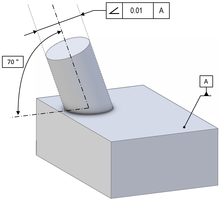
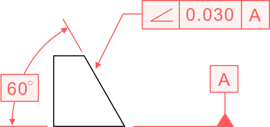
Let’s imagine a simple example to make this crystal clear. Picture a metal block with a slanted top surface. This is our controlled surface. The bottom surface is perfectly flat and will be our Datum A. The designer wants the top surface to be at a precise 30-degree angle to the bottom.
On the drawing, you would see a drawing callout pointing to the top surface. This feature control frame, or angularity callout, would show the Angularity symbol (which looks like an angled line), a tolerance value of, say, 0.2mm, and the datum reference ‘A’. Elsewhere on the drawing, the 30-degree angle would be shown in a box, making it a basic dimension.
What does this all mean? It means the entire surface of the top face must lie between two parallel planes that are only 0.2mm apart. And these two planes are tilted at a perfect, theoretically exact 30-degree angle relative to the datum plane.
Relation to Other GD&T Symbols
It helps to think of Angularity as part of a family. Perpendicularity (ensuring something is at a perfect 90 degrees) and Parallelism (ensuring things are at 0 degrees, or perfectly aligned) are just two kinds of Angularity. They all work in a similar way to change direction. The only difference is the angle they are controlling.
You could use the Angularity symbol and set a basic angle of 90 degrees, but the Perpendicularity symbol makes drawings easier to understand. This whole group of controls is also connected to Flatness.
Angularity is like “orientated flatness.” Flatness only checks to see if a surface is flat on its own. Angularity checks to see if a flat surface is flat and if it is tilted at the right angle to its datum plane.
Angularity vs Flatness
It’s easy to get Angularity and Flatness confused, but there’s a simple way to tell them apart. Think of Angularity as “Flatness with a direction.” Flatness just cares about how flat a surface is in relation to itself. You could have a perfectly flat surface, but it could be tilted at any old angle. It doesn’t need a datum.
Angularity, on the other hand, controls two things at once. It controls the flatness of the surface AND its orientation at a specific angle to a datum. It’s a much more powerful control.
Sometimes, you might see a modifier symbol for a tangent plane. This is used when you care more about the general angle of a rough surface and less about every little bump and valley.
Angularity vs Perpendicularity and Parallelism
As we touched on earlier, these three controls are like siblings. Perpendicularity and Parallelism are simply special cases of Angularity. The only difference is the angle.
Parallelism: The basic angle is 0 degrees. The tolerance zone is parallel to the datum plane.
Perpendicularity: The basic angle is 90 degrees. The tolerance zone is at a perfect right angle to the datum plane.
Angularity: The basic angle can be anything other than 0 or 90 degrees.
They all use the same core concept of a tolerance zone made of two parallel planes (or a cylindrical tolerance zone for an axis) to control the orientation of a feature.
Angularity vs Angular Dimensions with Tolerances
This is a really important distinction. Why not just put a plus-or-minus tolerance on the angle, like 30° ±1°? This is called an angular tolerance, and it creates a very different kind of tolerance zone.
It creates a wedge shape that gets wider the further away you get from the corner. This method doesn’t control the flatness of the surface at all. A surface could be perfectly angled but wavy like a potato chip and still pass.
The Angularity geometric tolerance is far superior. Its tolerance zone of two parallel planes has a constant width. This controls the angle indirectly while also controlling the flatness of the entire surface. It provides a much more complete and functional control, ensuring parts will actually fit together as intended.
Conclusion
So, there you have it. Angularity might seem complex at first, but when you break it down, it’s a really logical and powerful tool.
It’s not just a simple angle tolerance; it’s a sophisticated orientation control that defines a tolerance zone using two parallel planes set at a basic angle to a datum.
This Angularity tolerance zone ensures that a feature, whether it’s a surface or an axis, has both the correct tilt and the proper form.
Understanding the Angularity geometric tolerance is a huge step toward reading engineering drawings like a pro and appreciating the clever thinking that goes into making sure everything fits and works just right. It’s a cornerstone of modern manufacturing.
Frequently Asked Questions About Angularity
Q:What is the tolerance zone for a flat surface?
A: The tolerance zone defined for a flat surface plane relative to a datum is two perfectly parallel planes. The entire surface must lie between these two planes. The distance between them is the tolerance value from the drawing.
Q:How does angularity work for a hole?
A: For a circular feature like a hole, angularity controls the center axis. The axis must stay within a cylindrical tolerance zone. This zone is tilted at the referenced angle to the datum, ensuring the hole is drilled straight.
Q:What does the number in the feature control frame mean?
A: The numerical value is the width of the tolerance zone, not an angle. It’s a linear distance. Sometimes, it’s modified by a symbol like maximum material condition, which applies the tolerance when the feature is at its largest.