| Hole Type |
Cross-Section Shape |
Primary Purpose |
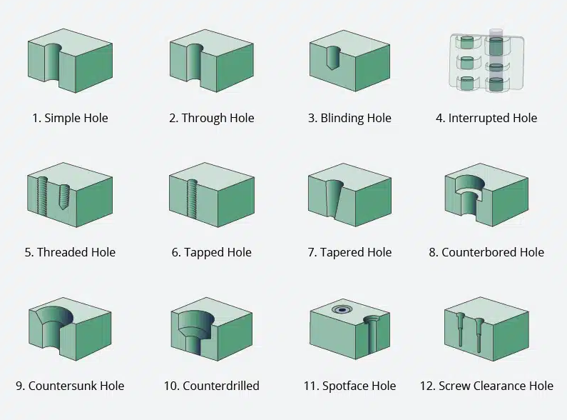
| Simple Hole |
Basic circular shape with a uniform diameter. |
Serving as a general passage or providing a basis for creating complex holes. |
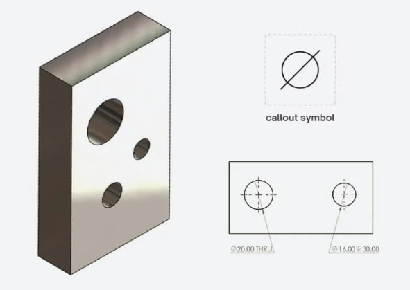
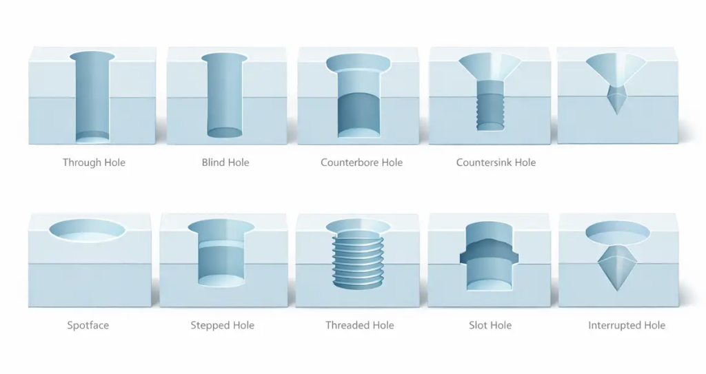
| Through Hole |
Tunnel passing through the entire thickness. |
Allowing bolts to pass completely through them, enabling nuts to be attached. |
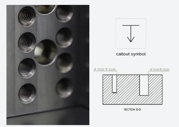
| Blind Hole |
Circular shape stopping at a specified depth.
| Creating holes that would otherwise cause one of the adjacent flat surfaces to crack. |
| Interrupted Hole |
A drilled hole that crosses an existing gap or void. |
Directing fluids or fasteners through hollow mechanical parts. |
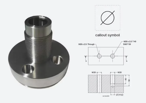
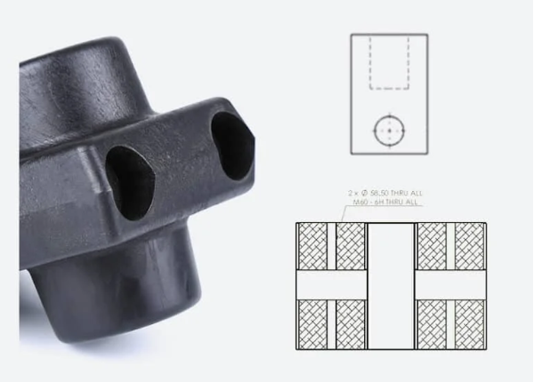
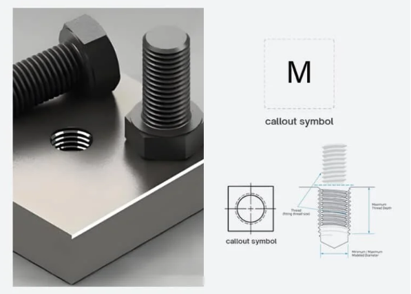
| Threaded Holes |
Walls featuring internal screw thread grooves. |
Attaching bolts or screws directly to materials without using a nut. |
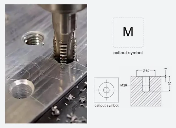
| Tapping Holes |
A hole with a slightly bigger diameter than the screw core. |
Providing accurate locations to start threading for blind holes. |
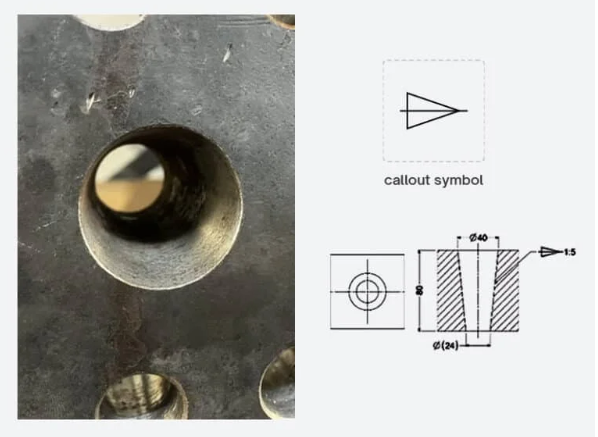
| Tapered Holes |
A conical shape that narrows along the axis.
| Creating leak-proof seals or self-centering fits for valves and pins. |
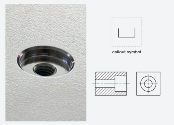
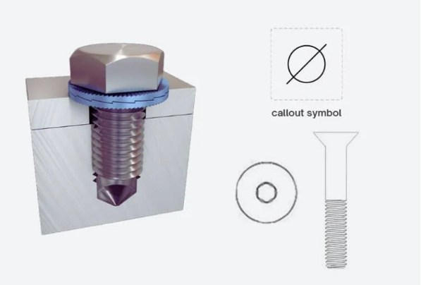
| Counterbore Holes |
A wide cylindrical step atop a smaller hole.
|
Enabling socket head screws to fit flush with or be recessed below a surface. |
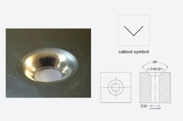
| Countersink Holes |
A conical hole at the opening of the bore.
|
Creating nut driver access for flathead screws on flat surfaces. |
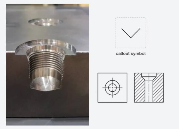
| Counterdrill Holes |
An angled transition between two diameters.
|
Providing surfaces for tool guide-ways or drilling clearances for drill points. |
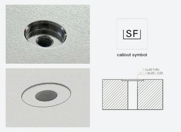
| Spotface Holes |
A shallow, flat-bottomed recess.
|
Providing smooth, even surfaces for installing washers on rough casting surfaces. |
| Screw Clearance Holes |
A hole slightly larger than the screw head or shank.
|
Creating space for a bolt to pass through freely to connect two mechanical components |
| Reamed Holes |
Extremely smooth walls with high precision.
|
Ensuring precise holes for high-tolerance press-fit pins and shafts.
|
|
Overlapping Holes |
Multiple intersecting holes in a pattern.
|
Weight reduction or creating specialized paths for fluid flow.
|