Have you ever read a list where the items just don’t match? It felt clunky and awkward, right?
In writing, we refer to these as parallel structures. When your list flows together so that you can connect all the elements with the same grammatical structure, it reads smoothly, and the meaning is clear.
In the engineering and manufacturing world, we have a similar concept; instead of words, we discuss surfaces and axes. We refer to it as Parallelism in GD&T, and it is a fundamental component of a language known as geometric dimensioning and tolerancing.
This is similar to how writing requires grammatical structure to convey a thought clearly; parallelism relies on creating parts that fit and work seamlessly. Let’s unpack what it is.
What is Parallelism in GD&T?
Parallelism in GD&T (Geometric Dimensioning and Tolerancing) is a type of orientation control that controls a condition in which a surface, plane, or axis is completely parallel to the reference datum.
Simply put, it controls how tilted one feature can get with respect to another. A perfect way to visualize parallelism is to think of two shelves on a bookshelf.
You want those two shelves to be perfectly parallel to each other; that is, you don’t want one of the shelves to be sloping away from the other and at an angle.
Your tolerance zone, controlled by the parallelism control, ensures that the controlled surface (in this case, one shelf) will not be too far from being perfect with respect to the datum surface (the other shelf).
Along with perpendicularity and angularity, parallelism is the clearest and arguably the most important of the other orientation controls, as it makes sense in terms of how parts relate to each other.
Parallelism Example
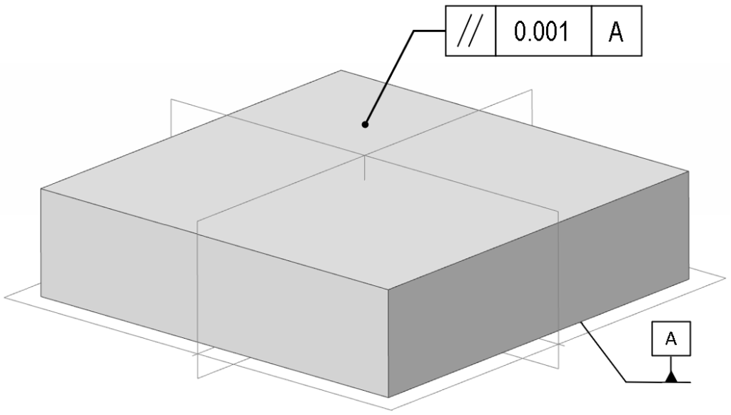
Let’s look at an example of parallelism that most can relate to for a clearer definition. Imagine you have a rectangular block with a top face and a bottom face. You want to ensure that the top face is parallel to the bottom face.
First, we need to select our reference. The bottom face can be called our Datum A. This is our reference, and our perfectly flat surface from which we will measure.
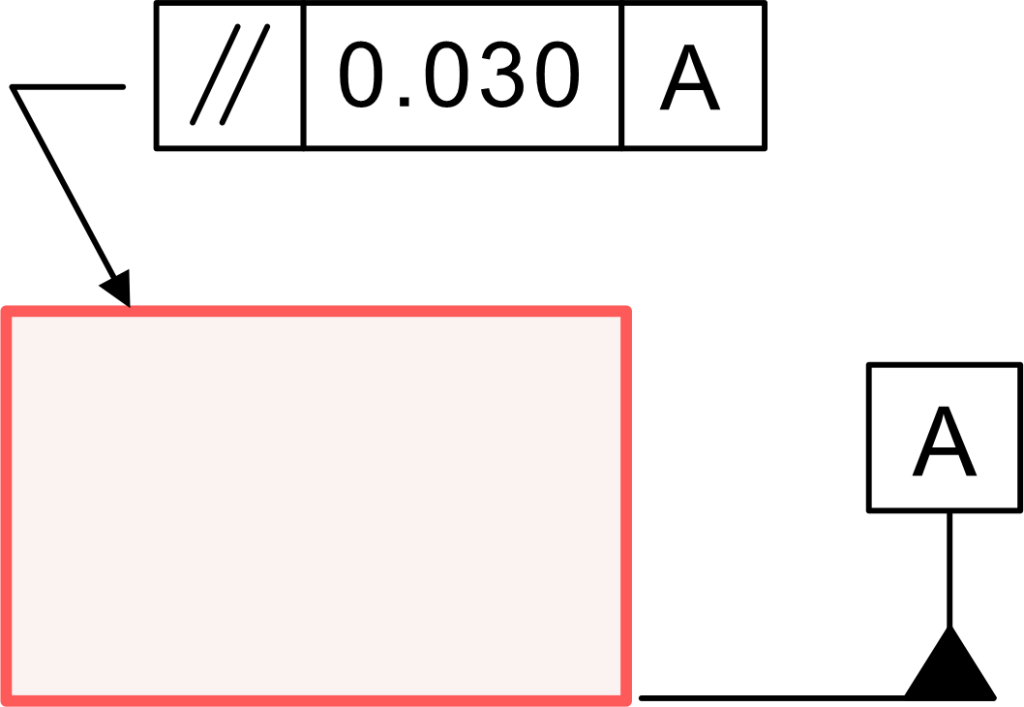
Next, we control the top face for location according to the engineering drawing. You will see a feature control frame pointing to the top surface of the block. It will look like this:
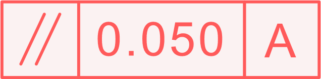
// | 0.05 | A
Let’s break down this drawing callout:
//: This is the symbol for parallelism. It basically looks like two parallel lines, which is easy to remember.
0.05: This is the parallelism tolerance value. Which means the controlled surface cannot be tilted more than 0.05 units (e.g., millimetres or inches) out of parallel.
A: This is the datum reference, which tells us, however tipped the surface is, it has to be parallel with respect to Datum A, our bottom face.
This simple parallelism callout conveys a very exact and critical requirement to the machinist and those inspecting them. It is core to the language of parallelism gd t.
Parallelism Tolerance Zone
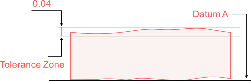
So, what does that 0.05 value in our example really mean? It defines the parallelism tolerance zone. It is an imaginary space where every point on the controlled feature must reside, as this is the area used to understand how we control the feature’s orientation.
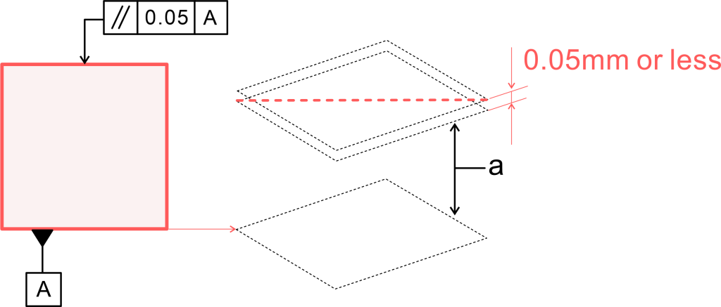
Surface Parallelism Tolerance Zone
The tolerance zone for surface parallelism consists of two parallel planes. In this example, we are establishing limits using two planes that are perfectly parallel to Datum A (A) and separated by 0.05. This means that the surface of the top face must lie between these two imaginary planes.
The controlled surface can be wavy or bumpy, as long as all of its highs and lows are contained inside this planar zone of 0.05mm in thickness. This defines the boundary of the planar surface.
Axis Parallelism Tolerance Zone
We can also apply parallelism to an axis, such as the centerline of a hole. For axis parallelism, the tolerance zone will be that of a cylinder instead. Imagine that we have a hole that needs to be parallel to a datum plane. The tolerance zone would resemble a perfect cylinder with a diameter equal to the toleranced value of 0.05 mm.
What we are controlling with this specification is that the axis of the manufactured hole must lie entirely within this imaginary cylinder. If we examine the feature control frame, we would see a diameter symbol (Ø) preceding the tolerance value (// | Ø0.05 | A), indicating that the zone is cylindrical.
How to Measure Parallelism?
Okay, so we know what it is, but how do we verify that the part actually meets the specification? You’ll have to measure the parallelism. There are three methods you can get this done:
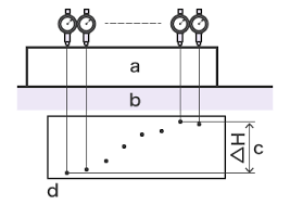
1. Dial gauges with surface plate for parallelism measurement
This is a classic, tactile method. You take your part and place the datum feature (such as the bottom face) directly onto the granite surface plate. The surface plate is a very flat, stable block that is a near-perfect datum simulator. Now, take a dial indicator that is mounted to a height gauge.
You want to softly touch the dial indicator on one side of the controlled surface and zero it. You then slide the dial indicator across the complete surface and record the desired readings.
Now, take the total motion from the lowest point of the needle to the highest point of the needle, which will be your parallelism measurement. As long as the total motion is within your tolerance specification, you are good to go.
2. Dial gauges with V-block to measure parallelism
When measuring the parallelism of the axis of the cylindrical part, a V-block is used. You will place the part in the ‘V’. The part remains stable within the ‘V’ shape, allowing you to place the dial gauge on the top face of the cylinder and move it along the part.
The total indicator reading provides the approximate parallelism error of the part’s axis with respect to the top surface of the V-block. You may also refer to the reading on the opposite side to better understand the variances in parallelism.
3. Coordinate measuring machines to measure parallelism
The modern high-tech method for measuring parallelism is through coordinate measuring machines (CMMs). CMMs use an accurate probe and physically touch the part many times. First, it will touch the datum plane, so it can then establish a mathematically ideal datum plane in software.
It will then measure some given number of points on the controlled surface. The CMM software will mathematically determine if all the measured points on the top surface are within the virtual tolerance zone of the defined user datum plane.
Parallelism and feature-of-size
When we apply parallelism to a feature of size (such as a hole or pin), we can define special modifiers in the feature control frame. The most common is the Maximum Material Condition (MMC), which is indicated by a Ⓜ symbol.
If we use MMC with a parallelism tolerance, the stated tolerance still applies when the feature is at MMC (for a pin, it is the largest size; for a hole, it is the smallest size). However, when the feature is away from MMC, you receive a bonus.
Using MMC to define a parallelism control is a valuable tool that allows for the manufacture of easier and less expensive parts while ensuring they can be assembled correctly. The orientation control is tied to the feature size tolerance.
Parallelism vs flatness
This is a very important comparison. Many people confuse parallelism and flatness, but they are not the same.
The biggest difference is that flatness is an individual control. A flatness tolerance only applies to that one surface and does not require a datum. It only controls how wavy or bumpy one surface can be.
Parallelism in GD&T, on the other hand, is a relational control. It always needs a datum. While it doesn’t really care about the flatness of the surface itself, it cares very much about its orientation with respect to the datum feature.
You could have a perfectly flat surface but with a tilt, and so it would fail a parallelism review. Alternatively, we could have a wavy surface, and while that surface passes a parallelism review because each high and low is contained within the two parallel planes defined by the tolerance.
Parallelism vs angularity
This is another important comparison within the family of orientation controls. You can think of it like this: parallelism is simply a special, more refined type of angularity.
Angularity is a geometrical tolerance that controls the orientation of a feature to a datum at any angle (except 90°, which is perpendicularity). So, for example, you could use it to control a surface at a 45° angle to its datum.
Parallelism is simply angularity at an angle of zero degrees. It is more restrictive. While you could technically use an angularity control to define a parallel relationship (using an angle of 0°), it’s far clearer and better practice to use the specific parallelism symbol.
Parallelism Feature Control Frame
The feature control frame (FCF) is the key component of any parallelism gd t callout. It is like a short sentence that conveys all the information you need. This tolerance frame always contains at least three compartments.
Geometric tolerance block
The very first compartment is the geometric tolerance block. This is where you place the symbol for the control you are applying. In the case of parallelism, it will always contain the two parallel slashes: //.
Tolerance block
The second compartment is the tolerance block. This displays the geometry and size of the tolerance zone. It contains the numerical tolerance value. If it is an axis being controlled, it will also have the diameter symbol (Ø) here. It may also contain modifiers, such as the MMC symbol (Ⓜ).
Datum block
The third and last required compartment is the datum block. This contains the letter that refers to the datum feature the control is associated with. If the feature must be parallel to Datum A, this block will contain the letter A.
Why is Parallelism GD&T Important?
So why do we go through all this trouble? Using a parallelism GD&T control is necessary for all the right reasons to have a product with all the right parts working correctly. It gives you an assurance that parts will fit together correctly, move together, and last longer, and it has the potential of saving you money (at least with respect to failures).
1. Ensure Assembly Compatibility
Let’s say two plates are to be bolted together. If those two surfaces are not parallel, you can expect a gap on one side (or more) of the assembly when one side gets tight.
When this happens, you create stress on the assembly and a potential leak (if there is a seal) in the assembly. Parallelism in GD&T ensures that mating parts are designed to fit perfectly together across the total surface area of the parts.
2. Optimize Motion Performance
When we think of parts that slide or rotate against one another, parallelism comes to mind immediately. Think of a piston moving inside a hollow cylinder (like an engine piston).
If the axis of the piston is not parallel with the axis of the cylinder, the piston will bind and scrape as it travels in the cylinder. This will create friction, wear, and/or destruction of the part. If the axes are parallel, the components can move together correctly.
3. Extend Service Durability
Parts that are not positioned properly with respect to one another will wear more in one area than another because only that area is receiving the entire load. This variation makes the part wear out and fail quickly (compared to a parallel surface).
An acceptable parallelism control ensures that loads are distributed properly across the surface intended to be loaded, which can drastically increase the service life of the assembly or at least reduce wear on it.
Conclusion
As you can see, Parallelism in GD&T is way more than just a symbol on a drawing. It is a tool to communicate your design intent (to a defined level of precision).
It ensures the orientation of a feature is completely controlled with respect to a datum and defines a clear tolerance zone to provide a non-ambiguous intention, which helps ensure that parts assemble correctly and function as intended.
Understanding the difference between parallelism and flatness, as well as how to read a feature control frame, is a fundamental skill to have.
While it may seem a little complicated at first glance, the logic of parallelism gd t is exactly what allows us to manufacture the machines we rely on daily to be reliable and complex. It keeps everything fitting together in a way that seems logical.