If something can be called a cornerstone of the modern manufacturing industry, it is CNC machining. It enables the production of high-precision components with complicated geometries.
CNC machining tolerances are an allowable variance in the dimensions and features of a part to ensure that the finished product satisfies the stipulated design criteria.
These manufacturing tolerances are essential to the survival of high precision and affect accuracy in dimensions, functionality, and quality control.
These tolerances compromise standard precision, manufacturing costs, and lead time. So, the greater the tolerance, the more complex the part to manufacture, and the lesser the tolerance, the part may not be able to perform.
This guide covers machining tolerances, emphasizing dimensional, geometric, surface finish tolerances, unilateral tolerances, and bilateral tolerances that present practical knowledge toward optimally tolerancing CNC-machined parts.
Types of Tolerances
You can categorize the tolerances in CNC machining into different tolerance types. Each type of CNC tolerance focuses on specific aspects of the surface characteristics and geometry of the part during the manufacturing process.
These standardized tolerance types include:
Dimensional Tolerances
Dimensional tolerances clearly define the allowed tolerance limits of the physical dimensions for a part, such as length, diameter, or width. To ensure the finished part falls within an acceptable range, they also set the maximum deviation from the nominal dimension.
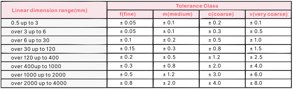
When specific tolerances are not indicated, standards like ISO 2768 provide general manufacturing tolerances for linear and angular dimensions.
Additionally, dimensional tolerances are further categorized into bilateral and unilateral tolerances so that mating parts can fit accurately. Understanding tolerances is necessary to make the right choice of material.
Bilateral Tolerances
Bilateral tolerances have variations in both directions that would be a plus or minus value from the nominal dimension. For example, a part might have a nominal dimension of 100 mm with a bilateral tolerance of ±0.05 mm, and its permissible deviation would be anywhere from 99.95 to 100.05 mm.
This type of tolerance is generally used for CNC-machined metallic parts or sheet metal, where there is room for minor variations.
Bilateral tolerance permits dimensional variations during machining, which are maintained dimensionally accurate. These tolerances are applied when slight deviations don’t affect the application, like structural applications or non-critical assemblies.
However, whenever bilateral tolerancing is specified, you must follow manufacturing methods because special care should be taken to keep the tolerance band to an amount that would satisfy requirements without causing an increase in manufacturing costs.
Unilateral Tolerances
Unilateral tolerances have allowable variation in only one direction from the nominal dimension: either above or below the specified value.
For example, a shaft with a nominal dimension of 50 mm and a unilateral tolerance of +0.1 mm/-0.0 mm must measure between a narrow range of 50.00 mm and 50.10 mm for optimal performance.
This type of tolerance is usually applied when a design requires the part to be of a maximum or minimum size; for example, in press-fit type assemblies.
Unilateral tolerances are often employed in CNC machining applications where there needs to be precise control of either an upper limit or a lower limit, such as an upper deviation or lower deviation in a bearing or shaft, so that the right components can fit there.
For example, a hole with a unilateral tolerance of +0.05 mm/-0.00 mm cannot be smaller than its nominal dimension to allow ease in the assembly of mating parts.
Likewise, maintaining unilateral tolerances demands extreme control over the machining process, with any variations in the cutting tools or material condition possibly affecting the achieved dimension.
Geometric Tolerances
Being a sub-branch of geometric dimensioning and tolerancing, these specific tolerances regulate the shape, orientation, and position features of a part.
Unlike dimensional tolerances that govern size measurement, geometric tolerances ensure that features like flatness, cylindricity, or true position conform to the intended position.
This means that between two points, position tolerance measures the deviation of the actual position, and profile tolerances control the contour of the surface with respect to the datum.
Geometric or profile tolerances become very important in complex CNC machined parts for which dimensional accuracy is insufficient. Thus, geometric tolerances in assemblies with tight requirements, such as turbine blades, ensure that actual components fit within tolerance limits.
Using GD&T, mechanical engineers could clearly express tolerance requirements based on international standards such as ASME Y14.5 or ISO 1101.
Surface Finish Tolerances
Surface finish tolerances govern the texture and quality of the surface of a part, measured as surface roughness (Ra). Surface roughness greatly influences CNC machined parts regarding friction, wear, and sealing.
In CNC machining, surface finish can achieve tolerances by selecting appropriate cutting tools, machining parameters, and post-processing like polishing or grinding.
Components with high precision have a surface roughness of Ra 0.8 µm. Rougher surfaces (Ra 3.2 µm) are used for less critical applications.
Additionally, you will need to use advanced CNC machines and precise control to achieve very tight tolerances for surface finish because the material’s condition and tool wear impact the results.
Standard vs. Tight Tolerances
Standard CNC machining tolerances, such as ±0.125 mm for milling and ±0.05 mm in turning, are used for mass production. Such standard machining tolerances have that ideal cost-precision balance for metal, plastics, or sheet metal components.
Tighter tolerances would be required for applications like aerospace, where holding dimensions to within ±0.005 mm is necessary. These are non-standard tolerances.
A tighter-tolerance machining process is complex and would require advanced CNCs, high-precision measuring equipment, and skilled operators. These tight tolerances ensure that deflection of the tool, thermal expansion of machines, and variations in material conditions or sizes are controlled.
In contrast to looser tolerances, tighter tolerances greatly affect the manufacturing cost and lead time. Limit tolerances specify the upper and lower limits of a dimension, that is, how much deviation is acceptable.
By way of illustration, any hole in an unusually specified 10 mm in diameter will be said to conform to limit tolerances of +0.02 mm/-0.00 mm if the actual measurement of the hole varies between 10.00 mm and 10.02 mm.
These tolerances allow the parts to remain inside the tolerance band.
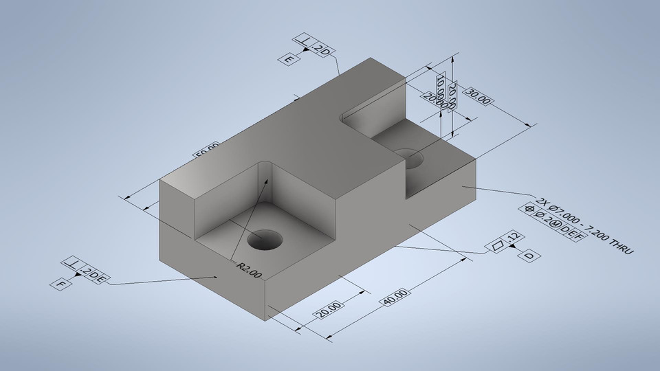
Geometric Dimensioning and Tolerancing (GD&T)
Geometric dimensioning and tolerancing (GD&T) is a standardized system that defines tolerance requirements in engineering drawings.
GD&T uses symbols such as flatness, concentricity, or actual position to determine geometric tolerances. This ensures that parts meet dimensional and functional requirements.
For example, symbols like parallelism ensure that parallel planes on a part maintain their intended orientation, preventing misalignment in assemblies.
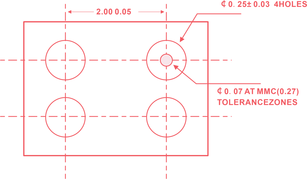
In addition, GD&T considers the maximum material condition(MMC), where a part has the maximum amount of material in its tolerance zone.
In CNC machining, GD&T is capable of producing high precision for complex geometries. For example, an angle can have a 0.1 mm cylindrical tolerance zone with respect to a datum to achieve true position in accordance with the desired position.
GD&T supports varied tolerances for varied features so that tolerances appropriate for function may be specified accordingly.
Factors Affecting CNC Machining Tolerances
Achieving a tight tolerance, or exactness in CNC machining, depends on three things: the material you use, the machine you have, and how you machine it.
Material Selection
Different materials significantly affect heat stability and how exact you can get. This exactness is known as CNC machining tolerance.
Metals like aluminum or steel are stiff, so you can make them with more precision, resulting in a tighter tolerance. However, softer materials like plastics can change shape with heat, so giving them a tight tolerance is harder.
Sheet metal is flexible, which means that it’s thin and bends easily, so when you shape it, it might not stay perfect. Additionally, a bending operation on sheet metal brings more variations, resulting in loose tolerances.
Harder stuff like titanium needs special cutting tools and slower work, which affects surface roughness and dimensional accuracy.
You must thoroughly learn about the material condition when determining tolerances because the finished part may have defects in the grain structure or residual stresses.
Machine Capabilities
Machining tolerances highly depend on the capabilities of a CNC machine. You can achieve around ±0.002 mm tolerances using CNC machines with high-precision spindles. Spindle runout, thermal stability, and repetition of the axis contribute to a standard precision.
The type of CNC machining process, whether it’s grinding, milling, or turning, affects the tolerance level you can achieve. For example, turning is ideal for tight dimensional tolerances, such as cylindrical parts, while milling is ideal for complex geometric tolerances.
As a result, these factors decide how precise the part can be and how much it costs to make it that way.
Machining process
Machining processes are critically important to achieve certain tolerances. The machining operation used-milling, turning, drilling, or grinding-affects the dimensional accuracy and quality of the finish of the final part.
Milling: Milling involves the cutting away of materials from workpieces by means of rotating cutters. It is quite versatile and very capable of machining complex shapes and features such as slots, pockets, and contours.
Milling is also good for geometric tolerances but potentially requires several setups with an intricate piece, which may induce slight variations. Typical tolerances range from ±0.05 mm to ±0.125 mm, with advanced machines being able to achieve tighter tolerances.
Turning: Turning produces cylindrical parts by rotating the workpiece against a stationary cutting tool. It is very good at holding tight dimensional tolerances-from ±0.01 mm to ±0.05 mm-which would be favorable to parts that need precise diameters or concentricity.
Drilling: Creates holes through the rotation of drill bits. Placing holds into dimensions with tool alignment and material properties determines these same factors. Normally, drilling tolerance is ±0.1 mm, yet high-precision drilling may go down to ±0.02 mm if set and equipped accordingly.
Grinding: Finishing operations made to fulfill very tight tolerances (to ±0.002 mm) with superior finishes (Ra 0.4 µm or better) with abrasive wheels. Grinding is good for the final finishing and precision requirement of parts.
Each operation has peculiarities that can affect dimensional accuracy, surface finish, and geometrical tolerances.
CNC Machining Tolerance Chart
The chart below provides a general guideline for tolerances achievable in CNC machining processes.
Document
Process
Standard Tolerance (mm)
Tight Tolerance (mm)
Typical Applications
Milling
±0.125
±0.005
General-purpose parts, complex geometries
Turning
±0.05
±0.002
Cylindrical parts, shafts, bearings
Drilling
±0.1
±0.02
Hole placement, structural components
Grinding
±0.01
±0.001
High-precision parts, aerospace, medical
Surface Finish
Ra 3.2 µm
Ra 0.4 µm
Sealing surfaces, wear-resistant components
In addition, remember than actual tolerances depend on material, machine capabilities, and process parameters.
Tips for Tolerances in CNC Machining
To optimize CNC machining tolerances, design engineers follow these principles:
Specify Appropriate Tolerances: Do not impose excessive tightness in tolerances because it can increase manufacturing cost, and time. The standards should observationally state optimal tolerances, where tighter tolerances are used for really critical features.
Incorporate Gd&T: Applying tolerances using geometric dimensioning and tolerances so that they satisfy functional needs without over-constraining the manufacture.
Consider Material Properties: Choose materials that can support desired tolerances but at the same time account for the thermal expansion, hardness, and machinability of the material.
Minimize Stacking of Tolerances: Design parts so that they minimize costs by reducing the cumulative effects of tolerances, which would otherwise cause deviations in assemblies consisting of multiple components.
Additionally, you must make sure the stated tolerances can be measured by standard measurement tools like calipers, micrometers, or CMMs; this will speed up the quality control process.
These principles help attain high precision at a reasonable cost in manufacturing.
Conclusion
CNC machining tolerances are essential in producing high-quality parts with great precision. These tolerances define the acceptable limits of variation in a part’s dimensions and geometry during the machining process.
Engineers can achieve exceptional dimensional accuracy and surface quality by choosing accurate tolerances and leveraging advanced CNC technologies.
This ensures that components meet the stringent requirements of industries such as aerospace and medical devices, where precision and reliability are critical.
FAQs
What is the standard tolerance for CNC machining?
The range relies on material conditions and machining processes. It is ±0.125 mm for milling to ±0.05 mm for turning. They are used generally for metal parts or plastic parts.
What is the position tolerance for CNC machines?
For high-precision CNC machines, position tolerances can be as tight as ±0.01 mm, depending on machine capabilities and part tolerances.
How accurate is CNC machining?
It is highly accurate, especially considering modern machines have tolerances as tight as ±0.002 mm. This accuracy results from machine calibration, material condition, and precise measurement tools.
What are the realistic tolerances for machining?
It is a range of ±0.05 mm to ±0.125 mm. You can use advanced equipment and process control for tighter tolerances of around ±0.005 mm.