In general, methods of designing and manufacturing low volume injection molding always follow a certain general direction. It’s all through the steps design, test, test the product, finalize it, and then delivery.
But according to each period that scientific technology creates difference and the more modern the technology. The more successful the product higher accuracy and aesthetics will be. At the same time, there is less waste and bring higher profits for businesses.
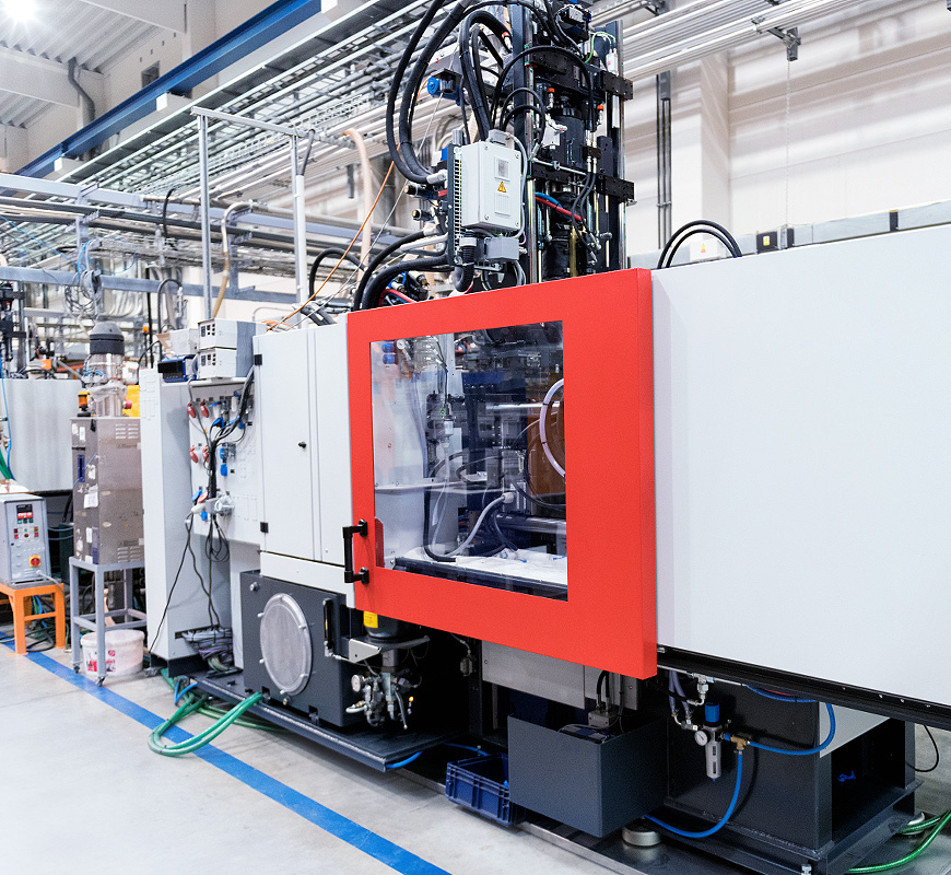
Injection molding is a type of mold used in the production line of plastic products. This type of mold has the main effect of shaping and fixing plastic products. With each type of mold, it will have a different shape and size. In which, the mold cavity is the most important part. It determines most of the quality of the finished product. To judge the quality of a set of injection molds, engineers can rely on the gloss and smoothness of the mold core.
Designing and manufacturing low volume injection molding is known for 2 methods:
Classic method: CAD – CAM – CNC – DELIVERY
Modern methods: CAD – CAE – CAM – CNC – DELIVERY.
1 – Traditional injection mold design and manufacturing process:
In this method, after designing in CAD (product design then design the mold), the mold will be fabricated and tested. If the test mold meets the requirements, it will be sent to mass production.
If the test mold does not meet the requirements, it will be re-checked in the next step mold making (mould repair); after that, try pressing the mold again, if the product is pressed out
If you still don’t meet the requirements, then you have to drop the mold and start over (design includes product design and mold design).
The traditional on demand injection molding design process is the main process mainly based on the accumulated experience from the previous design process hours (or trial and error) so the failure rate is quite high and costly time and cost.
2 – Modern low volume injection molding design and manufacturing process:
This method is an improvement of the classical method based on development of information technology. This process significantly reduces costs and errors in design and manufacturing, thanks to CAE-enabled software.
The modern method is a little different from the ancient method dictionary. Both methods are computer-based, but in the classical method will be processed and tested after design. In the process modern, will simulate and test by CAE on the computer. If the result If it’s good, we’ll make the mold and if it’s not, we’ll check and redesign it.
Once the mold is made, the process is the same as the classical method.
In modern low volume injection molding design process, failure rate is reduced down a lot because when making molds, no longer rely on experience where all specifications are calculated and simulated in advance through software, so the cost is very low.
Tasks of the steps in the process:
1. CAD:
Product design
Design products can be provided by customers or designed by themselves, CAD is used to perform the following tasks:
Design contours, geometric shapes of products by 3D simulation.
Technical analysis of the product, details, (conditions of corners, angles mold release, thickness…).
– Publish technical drawings.
Mold set design for Low volume plastic parts
– Work, order figures: Low volume plastic parts design, quantity, material product material.
– Data on plastic injection machine: Injection pressure, clamping force, plastic capacity, jig sizes.
Mold type
– Shrinkage: Determine material properties, wall thickness.
– Mold material: Material type of each part, hardness.
– Mold cavity and convex part (negative – positive mold): Solid or assembled.
– Arrangement of mold cavity: Number of mold cavity, layout, position.
– Cross-section of the channel: Round, semi-voluntary, trapezoidal, channel hot plastic.
– Guide and plate positioning: Positioning by cone, guide post, ring pin locate.
– Design and layout of the exhaust system.
– Export drawings or design files.
2. CAE:
CAE (Computer Aided Engineering) is the use of computer software computer to simulate and test the following technology and product characteristics when designing. CAE brings many benefits to machining and manufacturing after that. CAE allows mold designers and manufacturers to shorten design time as well as cost in mold manufacturing.
CAE with the following jobs:
– Analysis of the flow of liquid plastic (plastic filling process inside the mold).
– Analyze the process of solidifying and shaping the product in the heart mold.
– Calculate the state of filling and heat dissipation.
Know the defects of the product.
Therefore, applying CAE analysis to this process to optimize design by simulation and calculation is important.
You can use software like: Moldflow Plastics Insight. This is Powerful and full-featured software. It provides tools for creating and processing
Powerful mesh management, selection and simulation of plastic conduction systems.
High quality injection mold
Besides, mold material is also an important factor in evaluating mold quality. Normally, injection molds using hot plastic channels will be made of steel. At that time, engineers can ensure rigidity and durability throughout the machining process. In addition, at present, to make this type of mold, CNC technology is integrated into the mold manufacturing process. Therefore, the precision of the injection mold will be guaranteed at the highest level.
Classification of injection molds
The hot plastic channel system is the system used for the injection molding process to create plastic products. Thanks to this system, the plastic after leaving the injection nozzle of the injection machine will move into the mold cavity in the heated channels. From there, the plastic flow in the channel will always be maintained in a molten state and can be ready to move into the mold cavity.
The outstanding feature of the hot plastic channel is that it overcomes all the limitations of the cold plastic channel such as length limitations or product forming ability. To do so, the manufacturer has used an injection system capable of controlling separate heat as in the system using hot plastic ducts.
Therefore, the entire plastic conduction process will take place at a stable temperature, without the appearance of plastic lumps during the production process.
With many outstanding features compared to injection molds using cold plastic channels, this type of injection molds using hot plastic channels is applied to products that require large sizes and high complexity. The ability to control heat is an effective tool to keep the liquid plastic at a constant temperature.
Injection mold using cold plastic channel
Injection mold using cold plastic channel is the type of mold used mainly for small-sized products. Because it still exists some limitations compared to the hot plastic channel system such as the ability to shape or control heat.
Basically, an injection mold using a cold plastic channel is composed of 3 main parts: the nozzle silver, the plastic channel and the nozzle. These Low volume plastic parts are designed in the most optimal way to ensure the quality of the plastic during the filling process.
With the nozzle silver element, it is the connection between the injection molding machine’s nozzle and the plastic channel. It is a supporting tool for the process of leading plastic into the mold system. With the plastic channel element, this part connects the nozzle bush with the nozzle. During the design process, engineers need to pay attention to the channel cross-section.
It will directly affect the quality of plastic products during processing
As for the nozzle part, it is the part that connects the channel with the mold cavity. The main function of the injector is to guide the plastic to fill the mold cavity.
The plastic channel, also known as the glue line, the runner is the connection between the nozzle and the pump port (gate). The plastic channel is responsible for leading the molten plastic from the nozzle branching to the cavity to fill the plastic into the mold cavity through the injection ports. Molds with a structure that sprays directly from the nozzle into the product do not have a plastic channel but only a glue tail.
Some principles to keep in mind when designing plastic channels
Plastic channel is a very important component that can directly affect product quality. Therefore, when designing plastic channels, it is necessary to adhere to some technical principles to ensure quality for most products. Here are some guidelines to follow:
Minimize channel cross-section variation.
Pay attention to the channel exit factor.
Optimized channel length so that the cavity can be quickly filled without losing pressure and heat during the filling process.
The size of the plastic channel is different depending on the type of material, depending on the mold structure. One side of the plastic channel must be small enough to reduce scrap, shorten the cooling time (affecting the cycle of the product), and reduce the clamping force. On the other hand, it must be large enough to transfer a significant amount of material to fill the cavity quickly and with little loss of pressure.
Compare some common plastic channel cross-sections
Round type is the best; this allows the best flow of material. However, the channel must be machined on both the fixed and movable parts of the mold, which is costly and time-consuming.
Trapezoidal type (Good) and intermediate type (Better) are also commonly used because these two types are easy to process, optimize flow and save time.
The remaining grades are not recommended due to the lack of optimal flow and rapid cooling of the material. If the material cools rapidly, the material in the mold does not have adequate compression, thus causing shrinkage or other disabilities.
Several factors affect the design and size of the channel
Plastic materials (plasticity, chemical composition, setting time, softening, softening temperature, temperature sensitivity, shrinkage, …)
Mold type (automatic or semi-automatic glue removal, temperature control system of the channel, number of products arranged on the mold …)
In fact, the plastic channel design is mainly used for the experience factor or inherited from the existing molds. This approach also applies to large companies because the risk is low. However, the limitation of applying experience designers will have difficulty when there are new and different projects. Applying the calculation method in this article will help the designer have a better foundation from which combined with the experience factor will give better results.
Some requirements to pay attention to when designing the channel
Fill the product in the shortest time
No mold sticking
The surface gloss of the channel is high
The resin moves quickly and follows the shortest path so that the loss of heat and pressure is minimal
The material enters the cavity at the ports with the same time, the same pressure and the same temperature
Saving materials, if the cross section is too large, the cooling time will increase, and if the saving is too small, the filling time will increase.
Do not obstruct the flow
Cycle filling time is the shortest
The plastic particles have the same flow rate…
In practice, channel design cannot always ensure the above requirements. However, the designer must always aim at the design goal so that the time for each cycle is the shortest, to limit the consumption of raw materials, to limit product defects.. while still ensuring the right standards for the channel guide.
For molds with complex structures such as multi-cavity molds, molds of many products of different sizes and weights on the same mold, simulation tools should be combined to avoid errors of extruded products.
To ensure that the plastic channel design does not exceed the allowed standards, we have a correlation table between 3 factors:
Channel length
Channel cross-section
Maximum wall thickness of the product
Current obstruction
When calculating the channel, the smaller the flow resistance factor, the faster the product filling process. Flow resistance is correlated with hydraulic diameter. We can evaluate the pipeline based on this correlation.
Author
Gavin Leo is a technical writer at Aria with 8 years of experience in Engineering, He proficient in machining characteristics and surface finish process of various materials. and participated in the development of more than 100complex injection molding and CNC machining projects. He is passionate about sharing his knowledge and experience.