Engineering Tolerance Explained: Definition, Types And Application

Engineering tolerance might sound like a complex term, but it’s actually quite straightforward once you grasp its significance. Simply put, engineering tolerance refers to the acceptable range of variation in a component or system’s physical dimension or property.

Imagine you are designing a machine or constructing a building. Everything needs to fit together just right, down to the tiniest detail. That’s where engineering tolerance comes into play.

In this article, I will take you through the importance of engineering tolerance, exploring its definition, its different types, and how it manifests in various applications. Whether you’re a budding engineer or simply curious about how things work, understanding engineering tolerance is fundamental to appreciating the precision and reliability of modern technology.

So, read on, and let’s uncover the mystery behind engineering tolerance and enhance your understanding of how it shapes the world of manufacturing and engineering.

What Is Tolerance in Engineering?

In engineering, tolerance typically refers to the allowable deviation or variation in the dimensions, properties, or performance of a component, system, or process. It essentially defines the acceptable range, otherwise known as tolerance upper and lower limits, within which a part can deviate from its intended design specifications without compromising its functionality or the overall performance of the system it’s a part of.

Engineering tolerance ensures that manufactured parts fit together properly, operate smoothly, and achieve the desired quality standards, reaching the tolerance upper and lower limits. Tolerancing is a critical concept that governs the precision and reliability of engineering designs and manufacturing processes.

Types of Tolerances in Engineering

Dimension Tolerances

Dimension Tolerances

This type of tolerance specifies the allowable deviation or tolerance limits in a component’s dimensions, such as length, width, height, diameter, etc. It ensures that the part’s physical size falls within acceptable tolerance upper and lower limits.

Let us explore the dimension tolerances a little further by defining the parameters that are used to define this type of tolerance;

Nominal Value

Nominal Value

The nominal value is the target or intended dimension specified for a component or feature. It defines the middle ground and represents the ideal size or measurement the part should have.

Lower Deviation

Lower Deviation

The lower deviation, also known as the negative deviation or lower limits, indicates the amount by which the actual dimension of the part can be smaller than the nominal value while still being acceptable. It represents the lower limit of allowable variation.

Upper Deviation

Upper Deviation

The upper deviation, also called the positive deviation, positive tolerance, or upper limits, denotes the amount by which the actual dimension of the part can exceed the nominal value while remaining within acceptable limits. It represents the upper limit of allowable variation.

Bilateral deviation

Bilateral deviation

Bilateral deviation refers to the total allowable variation in both directions (above and below) from the nominal value. It is calculated as the sum of the upper deviation and the absolute value of the lower deviation. In other words, it represents the range within which the actual dimension can vary while still meeting the specified tolerance requirements.

A Basic Example of Dimensional Tolerance

Let’s consider a simple example of a cylindrical shaft with a nominal diameter of 20 mm and a specified dimensional tolerance.

Nominal Value: 20 mm Lower Deviation: -0.05 mm Upper Deviation: +0.05 mm

In this example, the nominal value is 20 mm, representing the target diameter of the shaft. The lower deviation is -0.05 mm, indicating that the shaft’s actual diameter can be up to 0.05 mm smaller than the nominal value. The upper deviation is +0.05 mm, meaning that the actual diameter of the shaft can exceed the nominal value by up to 0.05 mm. The bilateral deviation, representing the total allowable variation, is 0.05 mm + 0.05 mm = 0.1 mm.

Based on this tolerance limits, the acceptable range for the shaft diameter is from 19.95 mm (20 mm—0.05 mm) to 20.05 mm (20 mm + 0.05 mm). Any shaft with a diameter falling within the upper and lower limits range would meet the specified dimensional tolerance requirements.

General Tolerances

General Tolerances​

General tolerances, also known as standard tolerances or general dimensioning and tolerancing (GD&T), provide a set of default tolerance values that can be applied to various dimensions in engineering drawings and specifications. These tolerances are typically used when specific tolerance requirements are not explicitly provided or when the application does not necessitate tight tolerances.

General tolerances are defined by international standards, such as ISO 2768 for linear and angular dimensions, and they vary depending on the size and complexity of the part, manufacturing process, material, and other factors. They provide a practical and cost-effective way to specify acceptable levels of variation in dimensions while ensuring that parts remain functional and interchangeable.
Key aspects of general tolerances include:

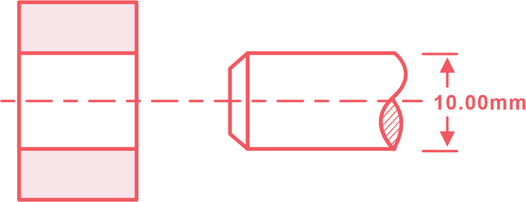
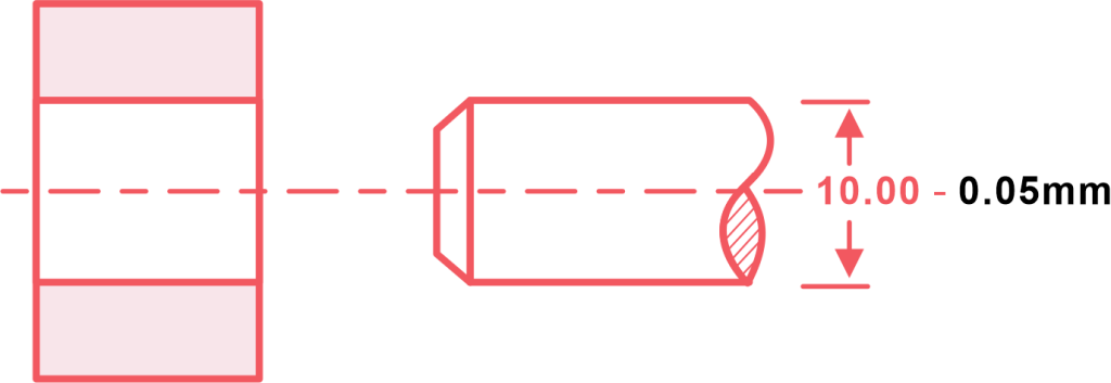
Size-Based tolerances: General tolerances are often specified based on the dimension’s size or scale. For example, smaller dimensions may have tighter tolerances than larger ones to account for the increased difficulty and precision required in manufacturing smaller features.

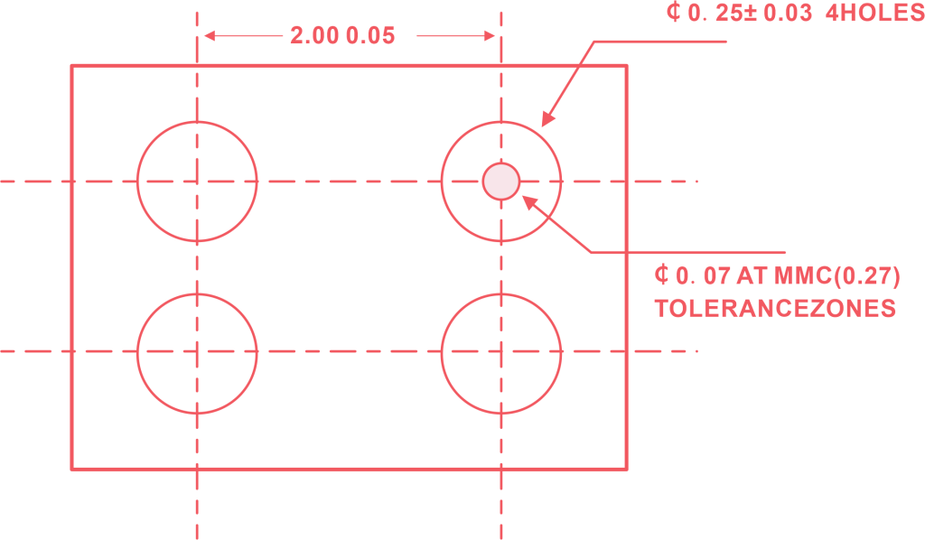
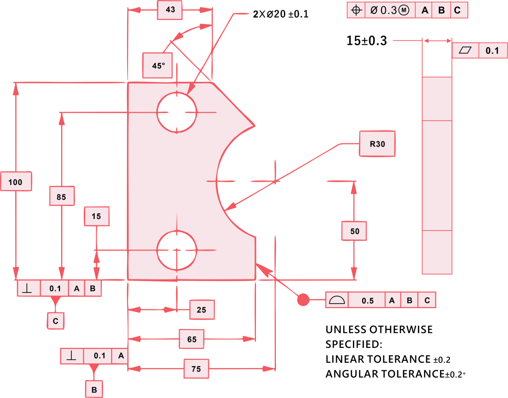
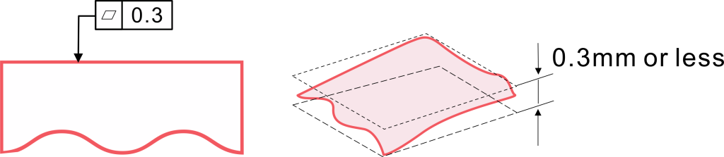
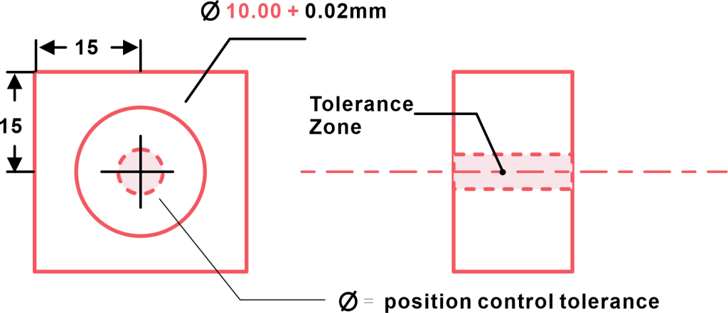
Geometric tolerances: General tolerances can also encompass geometric tolerances, which define acceptable standard deviation in the form, profile, orientation, and location of features on a part. These geometric tolerances ensure proper fit, assembly, and functionality of components within an assembly.

Application flexibility: General tolerances provide flexibility in specifying tolerance limits for dimensions that do not require tight control or where exact precision is not critical for the functionality of the part or assembly. This allows designers and engineers to focus on critical dimensions and features while maintaining overall manufacturing efficiency and cost-effectiveness.

Common standards: General tolerances are based on widely accepted standards and practices established by organizations such as the International Organization for Standardization (ISO) and national standards bodies. These standards ensure consistency and interoperability across different industries and regions.

Complementary to specific tolerances: While general tolerances provide default limit values for dimensions, they can also be used in conjunction with specific tolerances specified for critical dimensions or features. This allows for a comprehensive approach to dimensioning and tolerancing that addresses both general manufacturing requirements and specific design considerations.

GD&T (Geometric Dimension & Tolerance)

Geometric Dimensioning and Tolerancing (GD&T) is a symbolic language used in engineering and manufacturing to communicate precise geometric requirements for features on mechanical parts and assemblies.

It provides a standardized method for specifying and controlling features’ form, orientation, location, and size, ensuring that parts meet design requirements and function properly in assemblies.

Integrating GD&T with Six Sigma methodologies can enhance quality management practices, streamline production processes, and drive continuous organizational improvement initiatives.

Form Tolerance

Form Tolerance

Form tolerance, a subset of geometric dimension and tolerance (GT&T), specifies the acceptable variation in the shape of a feature or surface relative to its ideal form. It ensures that a part’s geometry conforms to specified straightness, flatness, roundness, and cylindricity requirements.

Each type of form tolerance addresses specific geometric characteristics and plays a critical role in ensuring engineered components’ functionality, performance, and interchangeability.

Straightness

Straightness tolerance defines the allowable deviation of a line or surface from a perfectly straight line. It ensures that a feature, such as a shaft or a beam, remains within a specified deviation limit along its entire length. Straightness is crucial for components that require precise alignment, such as shafts in rotating machinery or rails in linear motion systems.

Flatness

Flatness tolerance specifies the permissible variation in the flatness of a surface relative to a reference plane. It ensures that the manufacture of surfaces, such as mounting flanges or sealing surfaces, remain within a specified deviation limit, maintaining contact and sealing properties. Flatness is essential for ensuring proper mating and assembly of parts in mechanical systems, such as mating surfaces of engine blocks or mounting plates.

Roundness

Roundness tolerance defines the allowable deviation of a circular feature, such as a bore or a shaft, from a perfect circular form. It ensures that the circularity of the feature remains within specified limits, preventing wobbling or eccentricity during rotation. Roundness is critical for components like bearings, where precise rotation and minimal friction are essential for proper functioning.

Cylindricity

Cylindricity tolerance specifies the permissible deviation of a cylindrical feature from a perfect cylindrical form. It ensures that the cylindrical surface remains within a specified tolerance zone, controlling variations in diameter, roundness, and straightness along the length of the cylinder. Cylindricity is vital for components like hydraulic cylinders or pistons, where tight seals and smooth movement are necessary for efficient operation.

Position Tolerance

Position Tolerance

Position tolerance, another aspect of geometric tolerance, specifies the acceptable deviation in the location or orientation of features relative to a specified reference point, axis, or datum.

It ensures that features such as holes, pins, or mating surfaces are positioned accurately within an assembly, facilitating proper alignment, mating, and functionality. Position tolerance includes various subtypes, each addressing specific aspects of positional accuracy:

True position

True position tolerance defines the allowable deviation in the location of a feature, typically represented as a point relative to a specified reference point or datum. It combines the tolerance zone size (diameter or rectangular area) and the allowable deviation from the theoretical or nominal position. true position ensures critical features are located precisely, facilitating proper fit and assembly in mechanical systems.

Coaxiality

Coaxiality tolerance specifies the permissible deviation in the coaxial alignment of two or more cylindrical features, such as holes or shafts. It ensures that the axes of the features remain concentric within a specified tolerance zone, maintaining proper alignment and preventing eccentricity or misalignment. Coaxiality is crucial for components like bearings or gears, where precise alignment of rotating elements is essential for smooth operation and minimal wear.

Concentricity

Concentricity tolerance defines the allowable deviation in the concentric alignment of two features, typically circular in shape, such as a shaft and a bore. It ensures that the centers of the features coincide within a specified tolerance zone, ensuring proper alignment and minimizing radial runout. Concentricity is important for components like shaft assemblies or pulleys, where accurate alignment of rotating elements is critical for performance and efficiency.

Symmetry

Symmetry tolerance specifies the permissible deviation in the symmetry of a feature or profile relative to a specified axis or plane. It ensures that the feature remains symmetrical about the specified axis or plane within a specified tolerance zone, maintaining balance and uniformity. Symmetry is important for components like gears or impellers, where symmetrical profiles are essential for smooth operation and balanced loading.

Fits

In engineering, fits refer to the relationship between two mating parts or components concerning the amount of clearance or interference between them. These fits are crucial for determining how well parts fit together, affecting assembly, functionality, and performance factors.

press fit vs slip fit

Here are the main types of fits:

Clearance

A clearance fit is a type of fit where there is intentional clearance or space between the mating parts when assembled. In other words, the dimensions of the shaft are intentionally smaller than those of the hole it fits into, allowing for easy assembly and disassembly. Clearance fits are used when freedom of movement or assembly flexibility is required, such as in sliding mechanisms or parts that need to be easily replaced or adjusted.

Transition Fit

A transition fit is a type of fit where the dimensions of the mating parts result in both clearance and interference. This means that, depending on manufacturing tolerances, the parts may have either a slight gap or a slight overlap when assembled. Transition fits offer a compromise between clearance and interference fits, providing some degree of interference to ensure a snug fit while still allowing for ease of assembly and disassembly. They are commonly used in applications where alignment accuracy and ease of assembly are important, such as in rotating shafts or gears.

Interference Fit

An interference fit is a type of fit where the dimensions of the shaft are intentionally larger than those of the hole it fits into, resulting in an interference or press fit when assembled. In other words, the parts are forced together, creating a tight and secure connection without clearance. Interference fits provide maximum contact between mating surfaces, ensuring excellent load transmission, alignment accuracy, and resistance to vibration or movement. They are commonly used in applications requiring a rigid and secure connection, such as in press-fitted bearings or gears.

What Does High Tolerance Mean in Engineering?

In engineering, “high tolerance” refers to a narrow or tight tolerance specification for the dimensions or features of a component. A high tolerance means the allowable variation from the nominal or target dimension is very small.

In other words, the manufactured part must closely match its design specifications with minimal standard deviation. High-tolerance components require precise manufacturing processes and strict quality control measures to ensure that they meet the specified tolerance requirements. These components are typically used in applications where precision, accuracy, and consistency are critical, such as aerospace, automotive, and medical industries.

What are the Most Common Tolerances?

The most common tolerances used in engineering include:

Dimensional tolerances: Specify the allowable deviation limits and average and standard deviation in the dimensions of a component, such as length, width, height, diameter, etc.

Geometric Tolerances: Control the form, profile, orientation, and location of features on a part relative to a specified datum and the statistical tolerance.

Surface Finish Tolerances: Specify the acceptable variation in a part’s surface texture or roughness.

Positional Tolerances: Define the allowable standard deviation limits in the location or orientation of features relative to a specified reference point or axis.

Angular Tolerances: Specify the permissible deviation in the angle between two features or surfaces.

Runout Tolerances: Define the acceptable variation in the circularity or concentricity of a cylindrical feature.

How to Choose the right Tolerance for your project

Choosing the right tolerance for your project needs careful consideration of various factors, including the application’s specific requirements, the manufacturing process’s capabilities, worst case tolerances, and the desired level of precision and performance. Here are some steps to help you choose the right tolerance:

Understand the application requirements:

Consider the project’s functional requirements, operating conditions, and performance expectations to determine the critical dimensions and features that require tight tolerances.

Evaluate manufacturing capabilities:

Assess the capabilities of the statistical tolerancing process, including machining, casting, forging, or additive manufacturing, to determine the achievable levels of precision and accuracy.

Consult industry standards and guidelines:

Refer to industry standards, specifications, worst case tolerance, and best practices, such as ISO standards or ASME Y14.5, for guidance on selecting appropriate tolerances for different types of features and applications.

Consider cost and time constraints:

Balance the desired level of precision with the project’s cost and time constraints. Tighter tolerances may cost more in manufacturing processes and longer lead times.

Consult with experts:

Seek input from experienced engineers, machinists, or quality control professionals who can provide valuable insights and recommendations based on their expertise and experience in statistical tolerancing.

What is process tolerance?

Process tolerance, also known as manufacturing tolerance or production tolerance, refers to the acceptable variation in dimensions, features, or properties of a part or product that can occur during the manufacturing process. It represents the range of deviations from the intended design specifications that are inherent to the manufacturing process and equipment used.

Process tolerance considers factors such as material properties, machining methods, tool wear, temperature variations, and other variables that can affect the outcome of the manufacturing process. It defines the limits within which the manufactured parts can deviate from the ideal or nominal dimensions while still meeting the required quality standards.

Understanding process tolerance is important since it is typically determined based on the manufacturing equipment’s capabilities, the operators’ skills, and the desired level of precision and consistency in the final product. Tighter process tolerances require more precise and controlled manufacturing processes, which may involve higher costs and longer production times.

Managing process tolerance is essential for ensuring that manufactured parts consistently meet the required specifications and perform reliably in their intended applications. By understanding and controlling process tolerance, manufacturers can optimize their production processes, minimize scrap and rework, and deliver high-quality products to customers.

Conclusion

In conclusion, understanding engineering tolerance is fundamental to appreciating the precision and reliability of modern technology. From defining the acceptable variation limits in dimensions to controlling the form, orientation, and location of features, engineering tolerance ensures that manufactured components meet design requirements and perform optimally in various applications.

By exploring the definition, types, and applications of engineering tolerance, we gain insight into its critical role in ensuring quality, functionality, and performance in engineering design and manufacturing processes. Whether it’s specifying tight tolerances for aerospace components or ensuring proper fit and alignment in automotive assemblies, engineering tolerance remains essential for driving innovation and progress across industries.

Author

Gavin Leo is a technical writer at Aria with 8 years of experience in Engineering, He proficient in machining characteristics and surface finish process of various materials. and participated in the development of more than 100complex injection molding and CNC machining projects. He is passionate about sharing his knowledge and experience.