Injection molding is a production technique widely used in manufacturing to make a variety of plastic products such as bottles, LIDS, parts, etc. Here are some guidelines for injection molding design:
Injection Molding Design Guide 1: Material Selection
Choosing the right plastic material is very important for injection molding. Considering the required strength, hardness, wear resistance, temperature range and chemical stability, choosing the most suitable material is vital.
When choosing a material for injection molding, there are factors to consider:
Physical and mechanical properties:
When selecting materials for injection molding, the required physical and mechanical properties, such as strength, hardness, wear resistance and chemical stability, need to be considered. Different plastic materials have different properties, so it is necessary to choose the right material according to the desired properties.
Appearance and texture of injection molding parts:
If the desired plastic product needs to have a specific appearance and texture, then the appropriate injection molding material needs to be selected. Some plastic materials have good surface quality and texture, while others are less suitable for making cosmetically demanding products.
Temperature Range:
When selecting injection molding materials, the required temperature range needs to be considered. Different materials have different melting points and softening temperatures.
Injection molding Cost:
Different materials have different prices, so you need to choose the right materials according to your budget.
Use environment of parts:
When choosing injection molding materials, environmental factors need to be considered, such as whether heat and corrosion resistance are required. The selection of appropriate materials can ensure that the manufactured products have good durability in a specific environment.
Injection Molding Design Guide 2: Part Design
Designing an injectable part is the key to ensure the success of injection molding. The design should take into account factors such as wall thickness, shape, size, and structure. The structure of the part should allow the plastic material to flow smoothly into the mold.
Here are some guidelines for the design of injection molded parts:
Wall Thickness Basics
Basic recommendation is walls should be no less than 40 to 60% of that of adjacent walls,
In place of thick walls designers should look to add ribs, gussets, or replace material with a stronger material,
Wall thickness value should be based on material in use,
Decrease wall thickness where possible to shorten cycle time and reduce the volume of the part,
Uniform wall thickness will help with uniform cooling and reduce defects,
Look to add coring to thick sections where possible.
Wall Thickness Material Chart
Document
MATERIAL
RECOMMENDED WALL THICKNESS
ABS
0.045 in - 0.140 in
Acetal
0.030 in- 0.120 in
Acrylic
0.025 in- 0.500 in
Liquid crystal polymer
0.030in- 0.120 in
Long-fiber reinforced plastics
0.075 in - 1.000 in
Nylon
0.030 in - 0.115 in
Polycarbonate
0.040 in- 0.150 in
Polyester
0.025 in - 0.125 in
Polyethylene
0.030 in - 0.200 in
Polyphenylene sulfide
0.020 in - 0.180 in
Polypropylene
0.025 in- 0.150 in
Polystyrene
0.035 in - 0.150 in
Polyurethane
0.080 in - 0.750 in
Rib Overview
Ribs should be added for structural support instead of increasing the Wall thickness,
Ribs should be orientated on the part perpendicular to the axis upon which a load could occur,
Rib thickness should be 50%-60% of the walls to which they are attached,
Rib height should be less than 3 times the wall thickness Minimal rib draft should be 0.25°.
Ejector Pin placement factors to consider
Place in areas where part likely to stick to mold,
Factors for this include texture and depth of wall and ribs,
Effective ejector pins need a flat area,
In most cases ejector pins are placed on a non-cosmetic side of the part as ejector pins leave ejector marks,
For the most part ejector pin placement is usually a minor concern at the early stages of a design.
Best practice type of gates
Tab
Common Gate
Great for materials with additives like glass filled nylon
Easy to make = cheaper gate
Hot tip
Reduce gate vestige
Geometry and material dependent
Good for geometry like gears
Gating location
Gate should be away from pins, cores, or other obstructions. Weld marks common if placed near these,
Gate should be placed in thickest wall area,
Gated areas will have high stress. Locate gate away from surfaces that need a finish,
Gate should be in an area that is easy to degate if gate requires degating.
Radius
Round corners(Radius) will reduce stress concentrations and fractures,
Inner radius should be at least the thickness of the walls,
External sharp corners are fine, but inside corners need to have radii,
Be sure to round corners with radius at the point of attachment
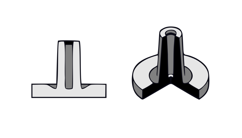
Snap Fits types
Cantilever Snap joints,
Torsion Snap Joints,
Annular Snap Joints.
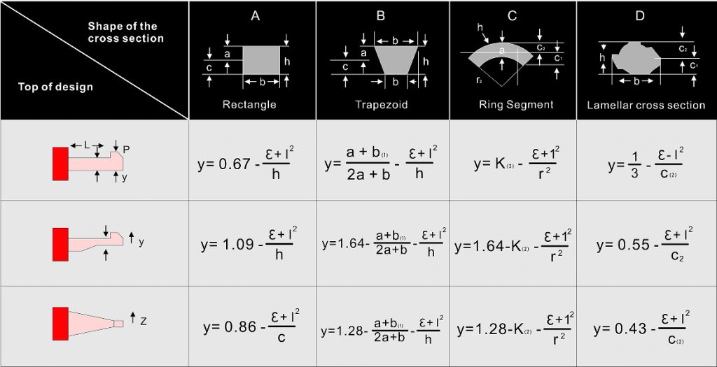
Snap Fit Calculations
E=Dynamic Strain(Unit less)
Y=Maximum Deflection(In, mm)
Ho= Thickness at base of finger(in,
mm) L=Length of Finger (in, mm)
Shrinkage
Mold Shrinkage should be designed onto the Mold by the mold designer,
Shrinkage varies for each material and datasheets should be referenced prior to mold creation,
Typically, an injection molded tool cannot mold 2 different materials with the same dimensional accuracy but there are exceptions.
Document
Physical
Condition
Test Method
Typical Value
Density
ISO 1183/B
1.06g/cm³
Apparent Density
ISO 60
0.66g/cm³
Melt Volume-Flow Rate (MVR)
220 ℃/10.0kg
ISO 1133
5g/10min
Molding Shrinkage-Flow
ISO 294-4
0.42 to 0.72%
Data sheets will vary but typically the shrinkage for each material can be found in a similar location as shown.