Introduction to structural design of plastic products

Home >  Blog >

Introduction to structural design of plastic products

Plastic Product Design

The history of the structural design of plastic products spans several decades, witnessing significant advancements and transformations in materials, techniques, and design methodologies.

The mid-20th century saw the introduction of new types of plastics, such as polyethylene and polypropylene, expanding the possibilities for structural design. Moldable and versatile, these materials enabled more complex shapes and designs.

During this period, advancements in molding and extrusion techniques allowed for more intricate and functional designs. Products became more consumer-oriented, with emphasis on aesthetics and usability.

Rapid prototyping and computer-aided design (CAD) revolutionized the structural design of plastic components. These technologies enabled designers to create detailed prototypes, experiment with complex geometries, and refine designs more efficiently.

Plastic Product Design Features

Designing plastic products differs significantly from other materials like steel, copper, aluminum, or wood. Plastic’s diverse material composition and versatile shapes offer more design flexibility than most materials. Unlike many others that are limited to specific shaping methods like bending or welding, plastics allow for more creative shape designs and manufacturing techniques.

However, the abundance of plastic material options also poses challenges. While over 10,000 types of plastics exist, only a few hundred are widely used. Plastic materials are not singular but composed of various groups, each with unique properties. This diversity complicates material selection and application in design.

Plastic Product Design Procedures

Medical Plastic Parts

To create a product that’s both efficient and cost-effective, collaboration among the appearance designer, mechanical engineers, draftsmen, mold makers, molding plants, and material suppliers is crucial from the start. No single designer possesses all the expertise needed. Insights from diverse perspectives are key to making the product practical.

Additionally, a systematic design process is essential.

The general procedure involves:

#1. Determine the functional requirements and appearance of the product

At the start of product design, the designer outlines how the product will be used and its necessary functions. This helps set boundaries for design choices, preventing future delays and expenses.

Here’s a product design checklist to confirm key factors.

(a) General information

(a-1) What is the function of the product?

(a-2) The combined operation mode of the product?

(a-3) Can the product mix be simplified by the use of plastics?

(a-4) Is it possible to be more cost-effective in manufacture and combination?

(a-5) Required tolerances?

(a-6) Space limitation considerations?

(a-7) Define the service life of the product?

(a-8) Product weight considerations?

(a-9) Are there any recognized specifications?

(A-10) Does a similar application already exist?

(b) Structural considerations

(b-1) What is the status of the load?

(b-2) The size of the load used?

(b-3) Life of the load?

(c) Environment

(c-1) At what temperature?

(c-2) Use of or exposure to chemicals or solvents?

(c-3) Temperature environment?

(c-4) Life span in this environment?

((d) Appearance

(d-1) Shape.

(d-1) Color.

(d-1) Surface processing such as biting, painting, etc.

(e) Economic factors

(e-1) Estimated product price?

(e-2) What is the price of the product currently designed?

(e-3) Potential for cost reduction?

#2. Draw preliminary design drawings

Once the product’s functions and looks are decided, the designer can sketch initial drawings considering the chosen plastic’s properties. These drawings help evaluate, review, and create prototype models ahead of production.

#3. Prototyping

prototype injection molding

The prototype model lets the designer physically assess the product and its engineering. There are two main ways to create prototypes.

First, using plate or rod materials, the designer constructs a model following a diagram. It’s quick and cost-effective, but testing and making changes are harder due to small quantities.

The second method involves temporary molds, producing a small batch. Although it takes longer and costs more, this method yields products closer to mass production. It allows for proper engineering tests and helps refine the final mold and production needs.

#4. Product Testing

During the prototype phase, designs undergo testing to compare calculations with actual performance. Most tests for product use can be conducted effectively using prototypes. This phase reveals how well the design meets functional requirements and allows for a complete evaluation.

Simulated usage testing starts during model production. Its value lies in how closely it simulates real conditions. Quickly measuring mechanical and chemical properties is crucial in evaluating model products.

#5. Design Recalibration and Revision

A review of the design will help answer some fundamental questions:

Is the product designed to achieve the desired effect? Is the price reasonable?

Even at this time, many products had to be discovered and improved for the economy of production or for important functional and physical changes. Of course, major design changes may require a complete re-evaluation; If all designs go through this careful review, the details and specifications of the product can be established at this stage.

#6. Develop Important Specifications

Specifications ensure consistency in production, ensuring the product meets appearance, function, and cost requirements. They clearly outline what the product needs, including manufacturing method, size tolerance, surface finish, parting surface position, raw edges, shape, color, and testing criteria.

#7. Open mold production

Accurate and thoughtful specifications enable the design and creation of the mold. Mold design should be meticulous, with input from experts. Poor mold design and manufacturing can raise costs, decrease efficiency, and lead to quality issues.

#8. Quality control

Regularly test manufactured products against a set standard. The test list should include all inspection items. Quality control personnel and designers should collaborate with the molding plant to establish a quality control procedure. This ensures products meet specification requirements during production.

Plastic Part Design Guide

Nominal Wall Thickness

injection molding wall thickness

Getting the wall thicknesses right is crucial in plastic injection molding. When plastic cools, it shrinks, causing issues like sink marks, voids, and warping. Thick parts pull inward, creating stress, while differences in thickness can lead to warping due to varying cooling speeds. Aim for uniform thickness to prevent these problems.

Draft Angles

Injection Molding Ribs

A draft angle is a slight slant on the vertical walls of a molded part. This angle helps the part to come out smoothly from the mold. It’s like a gentle slope that makes the release easier. Draft is needed for parts to properly eject from the mold. It’s an angle that allows the part to taper for an easier release. Usually, a minimum of 1/2 to 1 degree is needed, but 1.5 to 2 degrees is more common.

Ridius

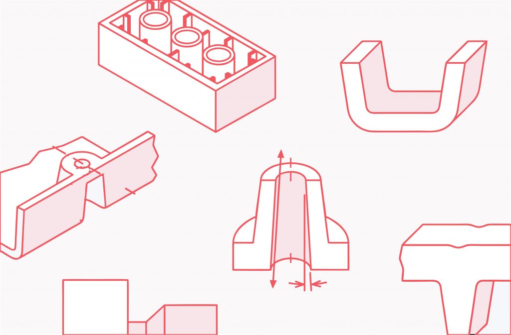
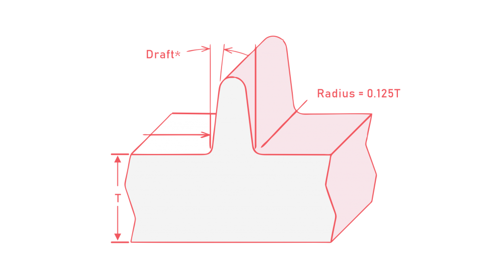
The radius in injection molding refers to rounded corners or edges in a part’s design. Using rounded edges instead of sharp corners makes the part easier to mold.

Proper radii reduce stress and the risk of cracks or warping during molding, making the part stronger. Rounded edges also help the part eject smoothly from the mold, avoiding damage.

When designing for injection molding, ensure adequate radii and avoid sharp corners for successful manufacturing.

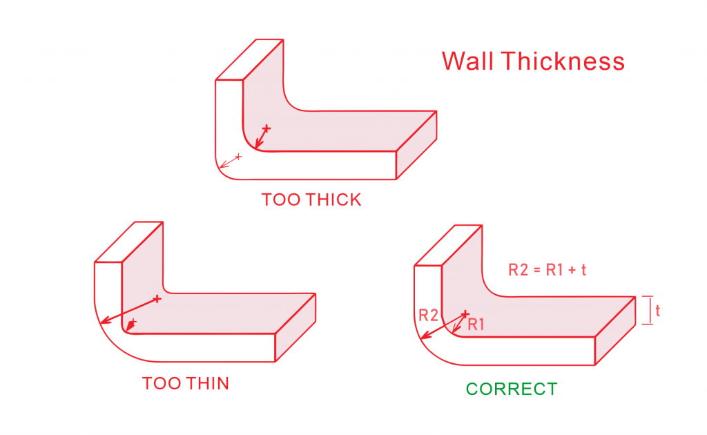
For corners, aim for a thickness around 0.9 to 1.2 times the nominal thickness to avoid stress and breakage.

Ribs, added for strength, should be thinner than the walls—around 60% to 80% of the wall’s thickness. Spacing ribs twice the wall thickness apart is ideal. More ribs enhance strength without needing larger ones. Keep rib height under three times the wall thickness, and if a thick rib is necessary, core its center for even thickness.

Gate Location

In a injection molded parts, the gate is where liquid plastic enters. Usually, there’s at least one gate, but many parts have several. Where the runner and gate are placed affects how the plastic molecules line up and how the part shrinks as it cools. This influences your part’s design and how well it works.

For straight parts, it’s best to put the gate at the end of a long, narrow section. If the part needs to be perfectly round, centering the gate is recommended.

Working with your plastic manufacturer team helps decide the best gate placement. Gates are crucial for the plastic to flow properly into the mold. They direct the resin from the runners through the part. The gate type and placement affect the overall quality of your part.

Holes

Holes in parts serve functions or help reduce their weight. Core pins make these holes by keeping the molten plastic away. There are two types: through holes go all the way, while blind holes don’t.

Blind holes are tougher as core pins have support only on one end. Making holes can cause defects or affect looks. Plastic flowing around the core pin might leave a visible line or weaken the part.

For small pins, blind hole depth should be twice the pin’s diameter, and for larger ones, it should be four times.

Keep a gap from hole edges to surfaces or other holes. Holes parallel to the mold opening are easier to make. Others might need special mold actions, which can increase costs.

Bosses

Injection molding Bosses

Bosses are added to plastic parts for assembly or mounting. Bad placement can affect wall thickness and the part’s looks, strength, or shrinking.

Thin walls around bosses should be 55%–65% of nominal thickness; thicker walls around 40%.

Boss height should stay under 2.5 times the hole’s diameter.

For boss design, the key is getting the diameter right—2 times the inside diameter is a good guide. If bosses are in flanges or higher up, coring them out helps material flow better during molding.

Mold Shrinkage

Mold shrinkage is when a plastic part becomes smaller as it cools inside the mold. When hot plastic is injected into a mold and cools down, it shrinks. This happens because the material rearranges and contracts as it changes from hot liquid to solid. Different plastics shrink differently based on their type, how they cool, the mold design, and how they’re processed.

Accounting for shrinkage is crucial in making molds and parts that are the right size. Designers often adjust the mold’s size or plan for this shrinkage to ensure the final part meets the needed measurements after it cools down.

Shrinkage during molding can be up to 20% by volume. Crystalline and semi-crystalline materials shrink more due to heat, while amorphous materials shrink less.

Author

Gavin Leo is a technical writer at Aria with 8 years of experience in Engineering, He proficient in machining characteristics and surface finish process of various materials. and participated in the development of more than 100complex injection molding and CNC machining projects. He is passionate about sharing his knowledge and experience.