Have you ever assembled flat-pack furniture cabinets, tables, or shelves, but the last screw just wouldn’t line up? You followed the instructions perfectly, pushing and pulling the parts, but they were simply too misaligned to fit together.
You went from being excited about your new purchase to crawling on your hands and knees, looking for some hidden flaw you missed to fit the parts together. This common real-world experience highlights a problem engineers encounter every day, called tolerance stacking.
In manufacturing, be it low-volume or high-volume, no part is perfect. There is always a tiny degree of acceptable variation in size and shape.
And while one small defect in a part may not be a big deal, the accumulated effect of the defects in each of the individual parts can cause a product to fail. It is like a tiny rounding error in a spreadsheet; you wouldn’t think it matters until it’s literally multiplied by a hundred.
This is where the understanding of tolerance comes into play. Tolerance is the secret language of engineering drawing specifications that ensures your phone, car, and other devices assemble, fit, and work as expected.
In this post, I will break down the specifics of what tolerance stacking is. I will explain why tolerance stacking is an important aspect of manufacturing, detail the methods used in a tolerance stack-up analysis, and share some tips and tricks to help you get it right.
What is Tolerance Stacking?
Tolerance is at its lowest, allowing engineers to understand the extent of variation in a final assembly. Put another way, it is a way to collapse all of the tiny errors from all of the individual parts into one final number.
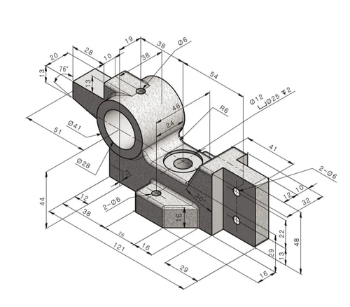
Every single part feature on an engineering drawing has a length or size dimension that you are already accustomed to. No manufacturing process is perfect, however, so each dimension has a tolerance – an allowable range of motion.
For instance, a standard rod could be made to a nominal length of 100mm, but the tolerance allows it to be made anywhere from 99.9mm to 100.1mm.
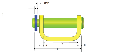
When there are multiple parts that fit together with individual tolerances of each of the mating parts, a tolerance stack can occur. The tolerances are cumulative. Given the cumulative nature of tolerances, it is possible that the total tolerances can amount to a degree of constituting that the final product would not fit together, or at worst, does not work!
Tolerance stack analysis is the systematic way of measuring the total amount of variation that may occur with a set of tolerances. The basis of a tolerance stack is to analyse all the dimensions in a sequence or stack, the total possible tolerances for a part, and estimate the assembly variation.
Why is this important for Manufacturing?
A tolerance stack analysis is important because it reduces the margin of error from what was designed to possible built. This gives designers confidence that their conception can be manufactured and function as intended.
Without a tolerance stack analysis, companies expose themselves to producing thousands of the same part, none of which fit together.
This is waste, costly rework for engineers, and maddening time delays. The aim is to ensure that every product unit that comes off the production line is inspected and meets the customer’s quality claims.
Hopefully, proper tolerancing stacks do assist in conveying design intent simply. It makes clear to everyone involved, from the engineer to the machinist, which critical features are most significant. It also helps manage balancing cost and quality. If we demand extremely tight tolerances on everything, we may make the manufacturing very expensive.
We could use tolerance stackup techniques to get to the sweet spot of tolerances that are loose enough for cost-efficient manufacturing, but tight enough to fulfil the performance limits of the product. This is simply managing dimensional variation to prevent problems from arising.
Types of Tolerance Stack Analysis
To predict and control the total variation in an assembly, engineers approach the problem in a few different ways. Each approach has its own advantages and disadvantages, and choosing the right approach is not only a factor of each approach’s advantages and disadvantages but is often determined by the application or risk.
Worst-Case Tolerance Analysis
The worst-case analysis is the simplest approach. As its name implies, you assume the worst-case scenario given the conditions of the assembly. To do this, you take the tolerances from each part in the stack up and add them together to calculate the maximum possible variation as if you assume everything is at its worst-case tolerance limits.
If we are stacking parts together, we must assume that every part is both at its maximum and minimum possible size.
The worst-case tolerance analysis also assures that if you follow the design, 100% of the assemblies will assemble and function. However, there is a price for these additional safety measures.
The worst-case tolerance also typically demands very tight tolerances, which could greatly increase the overhead cost associated with manufacturing the parts. Statistically speaking, it is very unlikely that all parts in a stack-up will be at the maximum limit, for example.
Statistical Tolerance Analysis
This is where statistical tolerance analysis comes into play. This approach uses statistics and comes up with a more realistic and usually more cost-effective approach. Instead of assuming the worst-case scenario, it takes the average variability and uses statistics to predict the eventual total variation we would likely see.
Most manufacturing operations can make parts dimensionally relatively close to their nominal dimension, and these dimensions likely fall into a normal distribution (% chances) statistical model (bell curve of chances) where most parts will see very little variation relative to nominal, and very few parts will, in fact, be nominal at their limit of the high of their tolerance range, or the low of their tolerance range.
A very common statistical analysis procedure is the Root Sum Squared (RSS), where it is much more than just adding tolerances; rather, with the RSS, you will take the square root of the sum of the squares of each tolerance. This method recognises that the chances of all parts achieving their maximum deviation at the same time are statistically improbable.
Although there are many other sophisticated approaches, such as Monte Carlo methods, that further illustrate the output and receive its assembly measurement through thousands of simultaneous computer-simulated scenarios.
In reality, the statistical tolerance technique should allow for more relaxed part tolerances, reducing manufacturing cost but achieving a very high level of quality.
What Are the Types of Tolerances?
If you look at an engineering drawing, you’ll see that tolerances aren’t just about how long or wide something is. Geometric Dimensioning and Tolerancing (GD&T) is a system that helps communicate design intent with accuracy. A feature control frame is a common way to show these.
Form tolerance
Form tolerance determines the configuration of an individual part feature, irrespective of other features. It doesn’t need a datum reference frame. It makes sure that a feature is what it should be. This includes:
Straightness: The degree to which a line element on a surface or an axis is straight.
Flatness: How flat a surface is, with no bumps or dips.
Roundness (circularity): How close a hole or pin is to being a perfect circle.
Cylindricity: Cylindricity controls how round and straight a cylinder is, making sure it doesn’t look like a barrel or a pointy end.
Orientation tolerance
Orientation tolerance controls how “tilted” one feature is in relation to another feature or a datum. It tells you what angle to put the parts or features together. The most common types are:
Angularity: This controls the angle of a surface or axis in relation to a datum.
Perpendicularity: A specific type of angularity that ensures a feature is exactly 90 degrees to a datum.
Parallelism: Makes sure that a feature is perfectly parallel to a datum plane or axis.
Location tolerance
One of the most common types is location tolerance, which is very important for making sure that parts in an assembly fit together. It manages the position of features in relation to each other or to a reference frame. This group has:
Position: The most common tolerance for location. It tells you where the centre, axis, or plane of a feature can be. Basic dimensions define the best place. A bolt hole pattern, for example, depends a lot on the true position tolerance.
Concentricity: This controls how well two or more cylindrical features line up with each other.
Symmetry: Makes sure that a feature is symmetrical around a central plane.
Run-out tolerance
Run-out tolerance controls how much a surface can change when a part is turned 360 degrees around a datum axis. It’s often used to keep parts that spin, like shafts or wheels, from wobbling or vibrating.
Circular Run-out: This controls how much a circular feature changes at any one circular cross-section.
Total Run-out: A more thorough check that looks at the variation across the whole surface as the part turns. It controls both the roundness and the cylindrical shape at the same time.
Best Practices for Tolerance Stacking
Following some important best practices can help you get the most out of your tolerance stack analysis. These tips will help you avoid common mistakes and make sure your designs are strong and easy to make, which will save you time and money in the long run.
Avoid Over-Dimensioning Your Part
It can be tempting to put measurements on everything when you make an engineering drawing. But this practice, called “over dimensioning,” can lead to problems.
It can make the design intent unclear and give the same part different requirements. Only dimension the important parts that the part needs to work correctly. Follow tolerancing rules to make sure that every dimension is clear and needed.
Evaluate Your Tolerance Stack’s Sensitivity
There are different levels of tolerance in a stack. Some will have a much bigger effect on the overall tolerance than others. A sensitivity analysis can help you figure out which part tolerances are the most important. You can focus your efforts on controlling these important dimensions by giving them tighter tolerances and letting less important features have more leeway.
Consider Post-Manufacturing Changes
The journey of a part doesn’t end when it leaves the machine. Things like heat treating, plating, or painting that happen after a part is made can change its size a little bit. If you don’t take these changes into account, your whole tolerance stack up could be wrong. Always think about how finishing processes will affect your assembly measurement and include that in your analysis.
Follow General Tolerance Best Practices
Finally, always base your analysis on what is real. Be sure you know what your company can make. It’s not helpful to set a tolerance that your machines can’t meet. Use a clear and logical reference frame to hold your measurements in place. To cut down on the number of parts in your stack-up, try to keep features that need to be closely related on the same part.
Conclusion
In engineering and manufacturing, learning how to stack tolerances is a game-changer. It’s not just a maths problem; it’s a way of thinking that makes sure products work right from the first build.
Engineers can avoid expensive mistakes, make better products, and design parts that are easy to make by knowing how dimensional variation affects things over time.
The goal is the same no matter which type of analysis you use: to make sure that every assembly meets its performance limits. You can use a worst-case analysis for critical applications or a statistical tolerance analysis for a more balanced approach.
You can make designs that work in the real world by following best practices and making your design goals clear. It’s a basic skill that makes a good design into a great product.
Are you ready to learn difficult things like this and do well in school? Join StudyFetch! You can be sure that you can handle any subject if you have the right tools and resources.
FAQs
Q: How does stacking tolerances work?
A:To find the total variation, tolerance stacking adds up the tolerances of each feature in a chain. We use this analysis to figure out how much space or interference there will be between parts in an assembly. This makes sure they will fit together and work properly before we start making them.
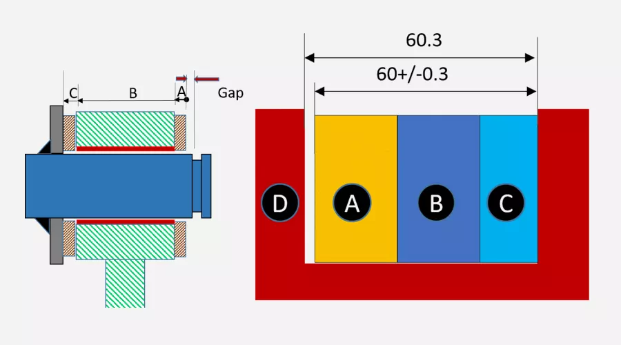
Q: What is an example of stack-up tolerance?
A: Think about putting three blocks on top of each other. The height of each block is 10mm ±0.1mm. If all of them are at their maximum (10.1mm), the worst-case stack-up tolerance would be 30.3mm. The total tolerance is the sum of the individual tolerances (0.1 + 0.1 + 0.1 = 0.3mm).
Q: How to learn tolerance stackup?
A: Before you can learn tolerance stackup, you need to know what GD&T (geometric dimensioning and tolerancing) is. Learn about the two main ways: worst-case and statistical tolerance analysis. To get better at tolerance stack analysis, practice with real-world examples and use software tools to do it on simple assemblies.
Q: What is a tolerance stack-up and why is it important in technical drawings?
A: Tolerance stack-up is the total effect of differences from the tolerances shown on technical drawings for each part. It’s important because it helps engineers figure out if an assembly will fit together correctly. These tolerances are used on an engineering drawing to show the acceptable limits of dimensional variation for manufacturing.