In Geometric Dimensioning and Tolerancing (GD&T), straightness is a basic form control that defines how closely a feature in a part conforms to a straight line. Another way to define straightness is the adherence to a specified straight line.
Straightness in GD&T regulates the linearity of surfaces or axes to ensure all deviations lie in the specified tolerance zone. Straightness does not require a datum and is a form control (tolerances that define the shape regardless of position).
Symbol of Straightness in GD&T
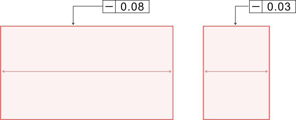
The straightness symbol in GD&T is a horizontal line placed in a feature control frame (FCF).
The GD&T symbol above denotes straightness control, followed by the respective tolerance value for the maximum allowable deviation.
The straightness callout in a part drawing ensures the feature remains within the specified tolerance zone. In technical drawings, the straightness symbol is positioned to clearly reference the controlled element.
The FCF is attached to the surface via a line for surface straightness. For axis straightness, it links directly to the size dimension with the maximum material condition (MMC) modifier to allow for a bonus tolerance.
What is Straightness In GD&T?
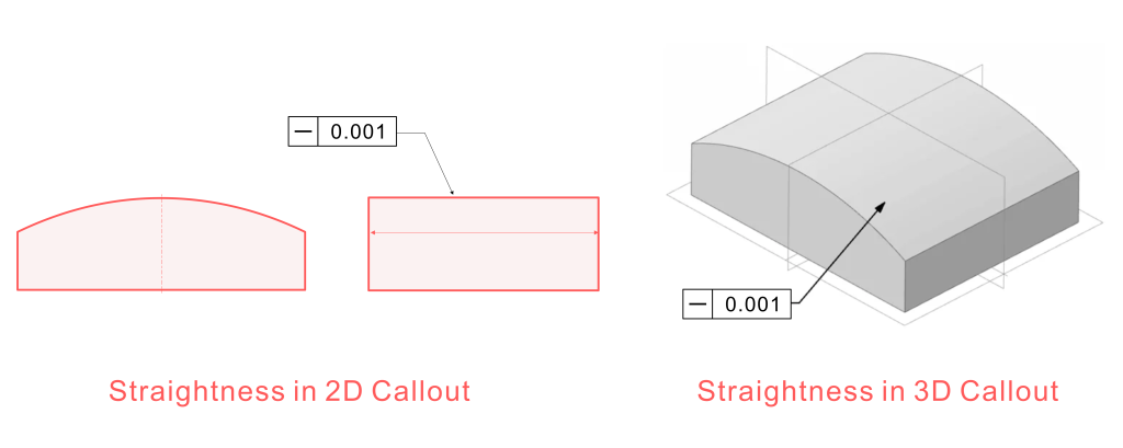
Straightness is a form of control that defines how closely a feature conforms to an ideal straight line. It can be used on surfaces and axes to make sure the deviations remain within a certain zone.
Surface straightness
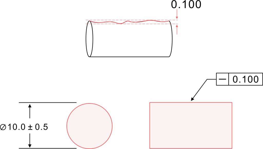
Surface straightness in GD&T is a form of control for the surface form of line elements on a flat surface or cylindrical surface. Surface straightness ensures the measured line lies between two parallel lines separated by the required tolerance value.
In simpler terms, the straightness control prevents waviness or any “bowing” that can affect sealing surfaces and create issues with mating part surfaces. For any flat surface, the surface straightness tolerance zone consists of two parallel lines, with the surface required to remain between these two lines.
Surface straightness is used in components like hydraulic sleeves, mating pipes, and cylindrical assemblies, where any dimensional deviation, specifically form anomaly, can cause leaks.
Axis straightness
Axis straightness in GD&T is also referred to as derived median line straightness and controls the linearity of the center axis of a cylindrical part. The derived median line is formed by connecting the median points across multiple cross sections along the length of the entire feature.
The cylindrical tolerance zone bounds this line, allowing the actual axis of the cylinder to deviate no more than half the tolerance value, generally.
The FCF is often attached to the size dimension at MMC to gain bonus tolerance from the diametric size. The function of axis straightness is to ensure the center axis remains straight, which is important for cylindrical parts.
Measuring axis straightness uses Coordinate Measuring Machines (CMM) to capture points and calculate the DML straightness.
How Straightness Relates to Form Tolerances?
Straightness in GD&T drawings is a critical form control, like flatness control, circularity, and cylindricity, which controls the form and shape without datum features like traditional dimensional tolerances.
Straightness control refines linear uniformity, while flatness control addresses planar uniformity across two dimensions. Straightness tolerancing can remove many other types of tolerance references, like profile.
Straightness tolerance is one of the four primary form controls. It differs in that it applies to a line element rather than an entire surface or volume. Straightness addresses linear deviation in one direction, usually in the orthogonal direction to other features.
Straightness Tolerance Zone
The straightness tolerance zone in GD&T defines the allowable deviation. Surface straightness consists of two parallel lines separated by a tolerance value within which the measuring line must lie. This is useful for flat surfaces.
Tolerance zone forms for straightness are two-dimensional for surfaces and three-dimensional for axis. The tolerance zone’s role is to ensure the surface adheres to the ideal surface position.
The tolerance zone for straightness depends on the type of control:
Surface straightness: Defined by two parallel lines.
Axis straightness: Defined by a cylindrical tolerance zone around the derived median line.
Explanation of Straightness Tolerance
Straightness tolerance is a numerical value that quantifies the maximum permissible deviation from a straight line, applied to surface elements or axes. The FCF contains the straightness symbol, tolerance value, and material modifiers.
This value defines the spacing between the two parallel lines for surface straightness. For axis straightness, it defines the diameter of the cylindrical tolerance zone.
The straightness callout ensures that the feature meets functional requirements.
Callout straightness may include material modifiers to allow bonus tolerance.
Straightness gd is typically measured without reference to datum features.
How To Measure Straightness Tolerance?
Measuring straightness tolerance requires the use of precise instruments.
Surface straightness can be measured using a height gauge or dial gauge. These gauges can record variations along the measured line, ensuring the total indicator reading stays within the tolerance value.
Axis straightness is measured using a CMM that probes points along the feature, constructing the derived median line, and assessing its fit within the cylindrical tolerance zone. A cylindrical gauge that matches the tolerance diameter can verify axis straightness with a simple fit test. If the part fits, it complies with axis straightness. However, the use of axis straightness prior to such tests ensures mating conditions are fulfilled.
Straightness vs flatness
Straightness is a localized form of control, but flatness runs across the entire surface.
Document
Feature
Straightness
Flatness
Applies to
Line element
Entire surface
Tolerance zone
Two parallel lines
Two parallel planes
Datum required
No
No
Measurement
Along a line
Across a surface
Straightness vs Profile of a Line
Straightness limits deviation along a straight line, while the profile of a line controls form and location relative to datum features. Profile of a line controls the shape of a curved or linear feature relative to a true profile.
Profile of a line encompasses curves and orientation, and complex round contours use profiles, while simple features can be completely defined using straightness.
Document
Feature
Straightness
Profile of a Line
Control type
Form only
Form + orientation/location
Tolerance zone
Parallel lines or a cylinder
Parallel curves around the accurate profile
Datum required
No
Optional
Why Use Straightness Tolerance?
Straightness tolerance helps you avoid errors on the shop floor and simplifies communication between designers and CNC machinists. Parts like shafts and bores require linear accuracy for features critical to proper assembly.
By refining size tolerances, straightness allows tighter fits and
Quality control by defining acceptable deviation.
Proper assembly by ensuring parts fit without interference.
Functionality of components like hydraulic sleeves, shafts, and bores.
Manufacturing efficiency by allowing bonus tolerance under MMC
Applying Straightness on Drawings
Where to place the FCF
The feature control frame is placed below or beside the size dimension. It extends to the feature outline.
It is placed next to the size dimension for axis straightness, indicating control of the center axis.
Using datums with straightness
Straightness does not require datums because it controls form control by itself. You can, however, use datum features on the same part with other tolerances for setups and inspections.
Example callout
A typical straightness callout for axis control might appear as
⏤ | Ø0.05 | MMC
This reads, a 0.05 diameter symbol cylindrical tolerance zone with bonus tolerance for a shaft.
ISO 1101 interpretation
ISO 1101 defines straightness as a form tolerance for axes and lines. It is important for the tolerance zones to be according to the ASME standards. The standard outlines:
Symbol usage and tolerance zone definitions.
Application to flat or cylindrical surfaces.
Rules for explicit and implicit specification in 2D drawings or 3D CAD models.
ISO 1101 emphasizes clarity in GD&T symbol placement and tolerance value interpretation
Conclusion
Straightness in GD&T is critical to ensuring the linear integrity of parts produced. Whether you use it for a flat surface, a cylindrical surface, or a derived median line, it plays a vital role in maintaining the functional geometry of parts that require mating and assembly.
FAQs
Q: What is the difference between straightness and flatness in GD&T?
Straightness controls a line within two parallel lines while flatness governs an entire surface between two parallel planes. Both do not require datum.
Q: What type of tolerance is straightness?
Straightness is a form tolerance, controlling linear deviation of a feature
Q: How to determine straightness?
Use dial gauges or coordinate measuring machines to measure deviations along a line. Make sure it fits within your defined tolerance zone.