CNC Machining Design Guide: Complete Guide 2023
Home > Blog >
CNC Machining Design Guide: Complete Guide 2023

CNC machining has completely changed the manufacturing process in many different industries by making it possible to produce complicated parts quickly and efficiently. Designing for CNC machining requires specific considerations to ensure the best results.
This guide provides an overview of key design considerations for CNC machining, including manufacturing tolerance, cavities and pockets, internal edges, thin walls, maximum size, holes, threads, the rational layout of parts and CNC machining undercuts.
Manufacturing Tolerance

Manufacturing tolerance is an essential factor to consider for CNC machining to produce accurate parts with proper functionality. The tolerance depends on the application and the purpose of the part.
For instance, aircraft or medical parts need top-level accuracy and tighter tolerances than consumer goods or aesthetic parts. To determine the suitable manufacturing tolerance, designers should consider the function of the form to be manufactured and the raw material’s characteristics.
Achieving the proper degree of accuracy and the required tolerance in CNC machining depends on several variables. Choosing the right cutting tools to fit the material’s qualities and the desired finish is one of the most important considerations. Post-processing methods like grinding, polishing or heat treatment can eliminate extra material, smooth the surface and increase the part’s dimensional accuracy. On the other hand, post-processing can also increase manufacturing time and cost, so designers should balance the desired precision level with the manufacturing process’s practical constraints.
Cavities and Pockets
Internal features of items are produced via CNC machining using cavities and pockets. They are commonly used in various aerospace, automotive and medical industries, where parts often require complex shapes and internal features. For example, cavities and pockets create intricate structures inside turbine blades and aircraft components. Another example is the medical industry, where cavities and pockets create implants and other medical devices with intricate internal structures.
Different cavities and pockets could be designed depending on the particular part’s needs. Depending on the machine tool used, a pocket might be created in a round or square form. In determining the machining strategy, the depth and size of the feature play a significant role. Other fundamental factors such as the machined material type, the required precision and finish and the available cutting tools would also influence the cavity and pocket design.
End mills and drills are frequently preferred in CNC machining to produce cavities and pockets. These tools might produce a wide range of features since they come in different sizes and shapes. For instance, a ball end mill might produce rounded pockets, while a flat end mill may be used to create square pockets. The right tool and machining technique must be chosen based on the desired feature’s size, shape, depth, and material being machined.
Internal Edges

Since they significantly impact the functionality and durability of a form, internal edges are an important component of CNC machining. The fillet, a rounded edge utilized to reduce stress concentrations and increase the overall strength of the item, is a typical kind of inner edge. They are frequently used in manufacturing turbine blades or automotive parts subjected to high stress or fatigue.
Another example of a typical internal edge is the chamfer. It is a bevelled edge used to soften sharp edges and improve the aesthetics of the form. They are frequently employed in consumer goods or architectural components when smooth and polished features are preferred.
Another type of internal edge commonly used is radii. An edge with a radius is employed to prevent sharp corners and improve the durability of the form. Radii are frequently used in gears or bearing components with smooth and uniform surfaces.
The selection of internal edges in CNC machining design is essential to achieving the desired functionality and aesthetics of the part. A proper type of internal edge should be carefully considered based on the part’s intended use and the machining capabilities available.
Thin Walls (Minimum Wall Thickness)

It is vital to consider the material and its qualities to ensure that thin walls can be machined properly. Different materials have different strengths and may require different wall thicknesses to maintain structural integrity. The manufacturing tolerances and precision of the CNC machine should also be considered.
To reduce the danger of deformation or failure, the thin walls’ design can be adjusted in addition to considering the material and machining capabilities. This can be done by adding reinforcements like gussets or ribs, a moderate taper to transition between thick and thin areas, or using fillets or radii to distribute stress points.
When designing thin walls for CNC machining, it’s important to consider both the limitations and capabilities of the production process and the product’s functionality and structural integrity. With the right preparation and optimization, thin walls can be effectively machined to create high-quality components.
Maximum Size
While designing an object for CNC machining, the maximum size restrictions of the machine should be considered. If the maximum size restriction is exceeded, incorrect machining and even machine damage may occur. Breaking the item into smaller sections that may be machined separately and later joined is a systematic approach to designing parts under maximum size constraints. Other production techniques that can handle bigger part sizes, including casting or forging, should also be considered.
The maximum size limitation depends on the material being machined. Raw materials like plastics may allow for larger part sizes compared to metals, thanks to their lower rigidity and weight. Therefore, consulting with the CNC machining service provider is important to determine the maximum size limitation based on the specific material and machine capabilities.
Holes
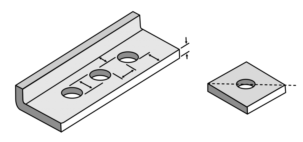
This CNC machining technique uses a spinning cutting tool or drilling bit to drill holes in a product. The hole accommodates screws and bolts most frequently and conforms to the dimensions of CNC drilling tools. The procedure is, therefore, typical of goods requiring component assembly. They also work well for aesthetic purposes.
The dimensions of the drill bit or end mill and the machining parameters would determine the accuracy and precision of the hole. Since it can affect the overall stability and strength, the depth variable should also be considered.
When designing holes for CNC machining, the hole’s location in relation to other components’ features must be considered. For instance, the distance between two holes or the position of a hole relative to an edge can affect the accuracy of the hole and the part as a whole. Careful planning and consideration of the hole design are necessary to guarantee the final item will perform as required and be accurate.
Threads

The threads used in CNC-machined items come in various kinds, each with unique characteristics and applications. The Universal Thread Standard (UTS), utilized in North America and based on the inch system, is one such form. UTS threads have a 60-degree angle and can be either external (male) or internal (female). The Metric Thread Standard is another popular variety based on the metric system and is utilized worldwide. Metric threads are identified by their nominal diameter and pitch and feature a 60-degree angle.
Another prevalent thread type in CNC machining is acme threads. Because of their high load-bearing capacity and trapezoidal shape, they are frequently employed in power transmission applications. Buttress threads, which have one side at a 45-degree angle and the other at a perpendicular angle, are also utilized in CNC machining. They are often employed in situations with heavy axial loads.
More thread types are utilized in particular applications besides those mentioned above. Pipe threads are used in plumbing and gas applications, whereas knuckle threads are utilized in articulating joints. It is essential to ensure the functionality and reliability of CNC machined parts by selecting the proper thread type and designing them correctly.
Rational Layout of Parts

A rational layout of parts refers to designing parts with an efficient and effective arrangement on the CNC machine bed. This might contribute to speeding up machining and increasing precision. Considering the part’s shape, size and orientation and optimizing the machining process parameters are two strategies that might be used to achieve a logical arrangement of components.
Additionally, designing parts with a rational layout can reduce material waste during the machining process. Less material is wasted, which lowers production costs if the pieces are organized to use the rawest materials.
Organizing comparable components into groups is another method for establishing a rational layout of parts. Applying such a method would contribute to establishing a logical part arrangement. It can also reduce the required tool changes, further reducing machining time and increasing efficiency and production costs.
Using computer-aided design (CAD) and computer-aided manufacturing (CAM) software might also help to achieve a rational layout of parts. These software programs can analyze the part designs and suggest optimal layouts based on the available sizes and requirements. This can help streamline the design process and ensure that the parts are arranged in the most rational way possible.
CNC Machining Undercuts

As the cutting tool cannot directly access the features with undercuts during CNC machining, there may be difficulties in both designing and manufacturing them. However, undercuts are necessary for creating certain parts with complex geometries, such as moulds or aerospace components. Using specialized cutting tools, such as ball end mills or undercutting end mills, is one technique to design components with undercuts. These tools have unique geometries that allow them to reach areas of the part that cannot be accessed with standard cutting tools. The accuracy and surface finish of the item could also be improved with these tools.
Specialized fixtures that could hold the part in place while allowing the tool to access the undercut are another way to design parts with undercuts. A vice with angled jaws can hold the part securely while allowing space for the cutting tool.
Another typical technique for CNC machining undercuts designing pieces with characteristics that may be utilized as supports. Bosses or ridges might support the cutting tool while it creates the undercut. The cutting tool may penetrate the workpiece more deeply by providing enough support without undue vibration or deflection.
Machining may be accomplished by employing a multi-axis machining strategy. Using a CNC machine with multiple axes of motion, the cutting tool can access the undercut from multiple angles. This method can decrease the requirement for specialized cutting tools or fixtures while improving the precision and surface polish of the component.
CNC Machining Services Best Practices
Best practices for CNC machining cover a range of design factors for optimizing CNC machining operations. These factors include, among others, choosing the right material, choosing the right tool, comprehending the machining process characteristics and designing for manufacturing tolerance.
Adopting these best practices in your CNC machining designs may produce excellent, precise, and effective components.
Material selection

Depending on the part’s needs, such as strength, durability, and corrosion resistance, select the right material.
Tool selection
Choose the right cutting tools for the machined material while keeping in mind the tool’s geometry, coatings and durability.
Machining Parameters
Understanding the machining process parameters, including cutting speed, feed rate and depth of cut, and optimizing them for machining material.
Design with Manufacturing Tolerance
While creating components, keep in mind the capabilities of the CNC machine and the cutting tools. This will help to guarantee that the parts are functional and fit together properly.
Part Orientation
While designing components, consider the maximum size of the machine as well as the form and characteristics of the part to save machining time and increase accuracy.
Support Structures
To stop warping or distortion during machining, add support structures to thin walls, overhangs and other characteristics.
Multi-Axis Machining
Employ a multi-axis machining strategy to reach features, such as undercuts, that can’t be machined with a straight tool path.
Post-Processing Techniques
Employ post-processing methods, such as grinding or polishing, to provide the appropriate surface quality and enhance the product’s functioning.
You can achieve high-quality, accurate, and efficient parts by incorporating these best practices into your CNC machining designs.
In conclusion, designing and producing components with undercuts in CNC machining might be difficult, but several strategies might be employed to get around these difficulties. By using specialized cutting tools or fixtures, designing parts with accessible support features or using a multi-axis machining approach, designers and manufacturers can create parts with complex geometries that meet the required specifications.
Author

Gavin Leo is a technical writer at Aria with 8 years of experience in Engineering, He proficient in machining characteristics and surface finish process of various materials. and participated in the development of more than 100complex injection molding and CNC machining projects. He is passionate about sharing his knowledge and experience.