Plastic injection molding forms the backbone of manufacturing processes for producing huge quantities of precision plastic parts. Industries such as automotive, medical, aerospace, and consumer electronics widely get their parts through injection molding.
Allowed specifications of tolerance are critical in ensuring that injection molded parts will meet stringent functional and assembly requirements.
Plastic moulding tolerances, especially injection molding tolerances, imply the acceptable limit of variation in part dimensions. This allows assembly and performance to be reliable, especially when there are many components involved.
This guide focuses on the definition of, importance for, types of, standards governing, and factors affecting plastic injection molding tolerances, thus serving as a detailed resource for the engineering and manufacturing professionals for their injection molding project.
What is Plastic Moulding Tolerances?
The tolerances in plastic injection molding refer to the permissible deviations the dimensions and physical attributes of injection molded parts can have from their nominal dimension.
Tolerances are expressed as + or – values, generally in metric (millimeters) or imperial (inches). Important parameters such as length, width, height, hole diameter, and concentricity are allowed a range inside which they can disperse.
Tight tolerances are required for high-precision applications, where any slight variation could cause functionality loss or assembly problems.
Injection molding tolerances generally has an acceptable range between ±0.1 and ±0.5 mm, depending on part geometry, material choice, and tolerance class.
These tolerances are established by standards promulgated by bodies such as the International Organization for Standardization (ISO) and the Society of Plastics Engineers (SPE).
Tight tolerance of some critical dimensions as low as ±0.025 mm can still be required in special cases. This necessitates the advanced design of molds and very accurate control of the process.
During injection molding, there should be maintenance of consideration in a number of process variables, such as material flow, injection pressure, and cooling, for dimensional control and retention of very tight tolerance.
Why are Tolerances Important for Injection Mold Design?
On account of injection molding tolerances being very crucial, they affect the aspect, operations, and life of the injection molded part. Injection molded parts are normally part of a complex assembly where exact dimensions are required for proper fit and performance.
Take medical devices for an instance. Tolerances have to be really tight for safety and efficiency. Automotive areas, however, require tolerances to be tight enough to withstand operational stresses like those brought about by extreme temperature changes.
If deviations remain outside allowable boundaries, tolerance stack occurs and combined variations from multiple components create alignments in assembly.
Besides greatly affecting the injection molding cost and feasibility, if strict tolerances are required, the price goes up because high-grade mold tooling has to be used. The machines employed in injection molding must be of the highest quality to hold tight tolerances.
Additionally, rigorous controls over all process variables must be implemented.
On the flipside, while somewhat relaxed tolerance might slightly reduce the cost of producing a molded part, it opens the door to defects such as surface sink marks and non uniform wall thickness, both of which are detrimental to overall product quality.
Engineers can balance quality and cost by setting desired tolerances during the design phase. This allows the manufacturing process to deliver reliable plastic parts.
Types of Injection Molding Tolerances and thier Standard
You can categorize Injection molding tolerances based on the specific features being measured. Each tolerance standard has been set as a manual for manufacturers. There are five primary types of tolerances.
Dimensional Tolerances +/- mm
In linear dimensions like length, height and width, dimensional tolerances help specify the how much variation is allowed. They help molded parts to fit within assemblies.
The standard injection molding tolerances for dimensional accuracy ranges from ±0.1 mm to ±0.5 mm and depend on the material properties and nominal dimension.
For applications requiring high precision, lower tolerances of ±0.025 mm are ideal because of critical dimensions. Due to this, you can develop precise process control and an advanced mold design.
Lastly, shrinkage rates are a characteristic of plastics that influence dimensional tolerances. You must consider it during mold design.
Straightness / Flatness Tolerances
Straightness and flatness tolerances accommodate deviations in the planarity and linearity of either a genuine plane or its corresponding surface. These tolerances are major when parts have large flat areas or when the object must come into contact with another surface uniformly. These tolerances generally range from ±0.1 mm to ±0.3 mm over each 100 mm of length.
Non-uniformity of wall thickness or an improper material flow can easily trigger warpage, which in turn affects straightness and flatness. Tight tolerances for straightness and flatness call for uniform cooling and extremely careful gate positioning on the mold surface.
Hole Diameter Tolerances +/- mm
Hole diameter tolerances are important for types of features like mounting holes or passages. They allow these to line up with fasteners or fastener bottoms or any other similar mounting components.
Usually, tolerances for hole diameter range between ±0.05 and ±0.2 mm, depending upon the size and materials involved.
To maintain hole diameter tolerances as tight as possible, it is necessary for mold tooling to be as precise as possible and for injection parameters to be consistent, thus minimizing variations caused by either increased shrinkage or thermal expansion.
Smaller holes may require finer tolerances of approximately ±0.03 mm so that they will function properly, for instance.
Blind Hole Depths Tolerances +/- mm
Dimension tolerances for blind hole depth specify the allowable variation in depth for holes that do not penetrate entirely through the material. These tolerances are necessary to fit threaded inserts and similar processes. Commonly, they range between ±0.1 mm and ±0.3 mm.
Factors like mold design and uniform cooling are all-important in preventing bending of the pin under high injection pressure, thus ensuring dimensional accuracy for blind holes.
Concentricity/Ovality Tolerances +/- mm
Concentricity/ovality tolerances make sure the cylindrical features like holes or bosses are separated from and in perfect alignment with each other. These are critical for any kind of rotations or mating interface. The typical range of tolerances is ±0.05-0.15 mm.
To achieve such tolerances, suitable mold design and injection pressure control must be maintained to eliminate any distortion from occurring during the molding cycle, particularly for highly complex part geometries.
Industry standards, for example SPI/PIA method, give detailed tolerance tables for materials such as ABS, polycarbonate, and nylon.
For example, ABS may have a commercial dimensional tolerance of ±0.100 mm for up to 20 mm, whereas the fine tolerance may be ±0.030 mm for more critical features like hole diameters.
Factors Affecting Injection Molding Tolerances:
Several factors influence the ability to achieve and maintain tight tolerances in plastic injection molding.
Design For Manufacturability (DFM)
Design for Manufacturability (DFM) is an essential way to make sure that parts are designed to effectively and correctly undergo injection molding. DFM tries to maintain a constant wall thickness of 1 to 4 mm in most areas so that the material flows and cools uniformly.
This would help reduce defects such as sink marks and warpage. Proper drafts, generally around 1-2 degrees, help eject the part without distortion.
DFM also adjusts the stack of tolerance by the optimization of the part geometry where critical dimensions are held to tight tolerances, hence further improving moldability.
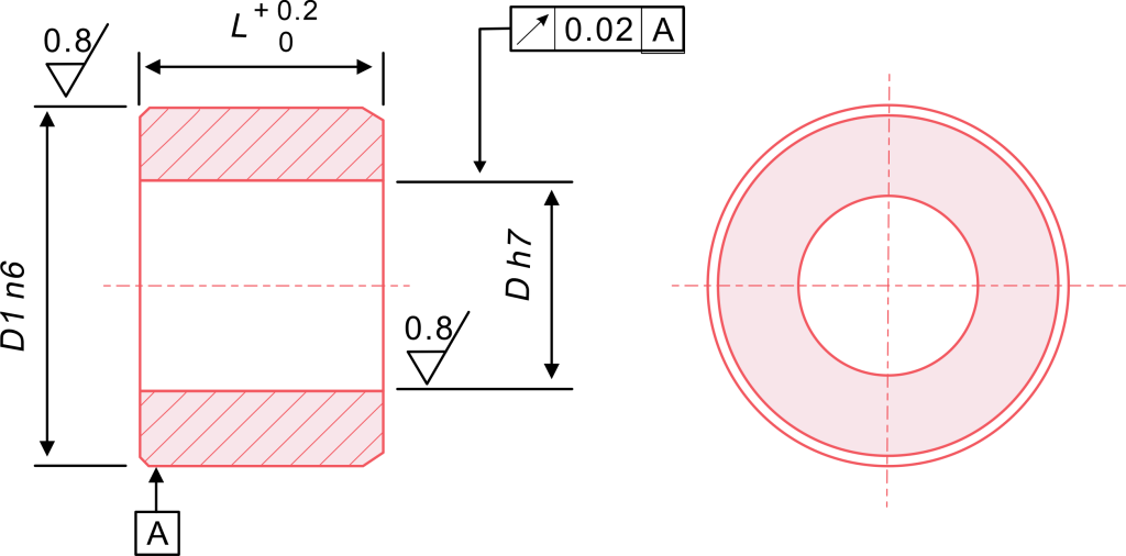
Mold Tolerances
Hardness of mold tooling is the prerequisite in determining the plastic injection molding tolerances. Molds are usually machined at tolerances of ±0.005 mm to ±0.025 mm and vice versa, depending on the required tolerances.
A highly-oriented mold design, CNC machined mostly, sets a minimum to maximum deviation allowed over the part dimension.
Mold-related features that are gate location, cooling channels, and parting lines require precision in their engineering so that material flow and cooling are both uniform and result in differences as minimal as possible.
Constant maintenance of molds should not be overlooked since any wear would cause deviations from the production standards.
Injection Molding Machines & Process Control
In most injection molding techniques, two molds are used-one is the male mold, and the other is the female mold. The male mold is generally thought of as the cavity, and the female mold as the core; in some rare instances, the opposite is true.
There are two halves to each mold, called top and bottom. The mold halves are closed in the molding press; the injected plastic material is injected into the mold surrounded by a cavity where the molten plastic cools and is cast into the desired shape.
Injection pressure represents the pressure applied to the molten raw material to fill the mold cavity. During the filling period, the injection pressure is the overriding factor.
Holding pressure is applied against the fluid to offset material shrinkage as the period of injection extends after the cavity has been filled. Holding time, also called pressurizing time, is simply the time during which the holding pressure is applied.
Modern injection molding machines carry temperature and pressure sensors for very prompt process control. Drying and temperature control and tight control of process parameters thus become paramount under such machines for their use with tight tolerance requirements.
The injected molten material should fill the mold cavity, pack it properly in a given period, and make sure no flash forms. To guarantee repetition, the process has to be analyzed by some process control techniques or statistical methods.
Material Shrinkage Values
With the different shrinkage rates, material selection largely determines the injection molding features. Amorphous plastics, such as ABS, generally have lower shrinkage rates of about 0.7–1.6%.
The resin and crystalline materials such as polypropylene, on the other hand, show a little too high approximate shrinkage rate of 1–3%.
The higher shrinkage leads to problems with dimensional accuracy and consequently requires mold compensation to be addressed. Moldflow trial can be done with a tool from Autodesk to predict shrinkage in different materials so that molds could be scaled accurately to achieve tolerances desired.
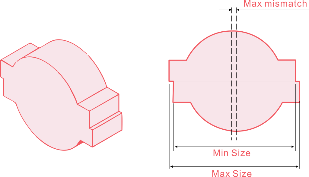
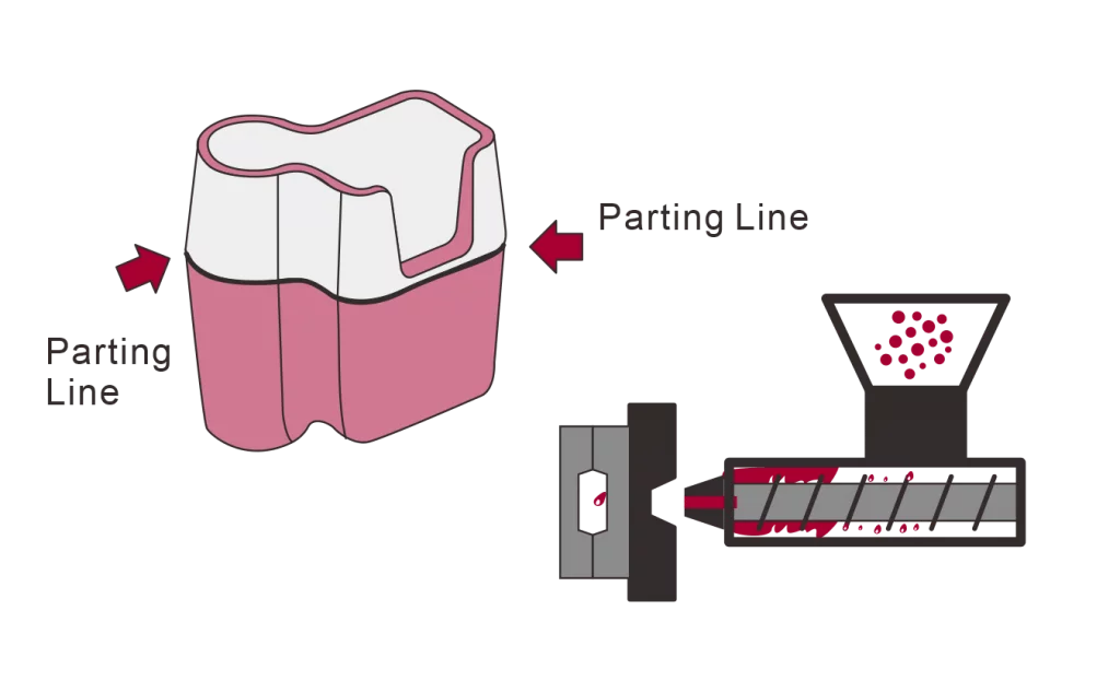
Parting Line
The line at which two mold halves meet is called the parting line and can bring in slight dimensional variations if misalignments or wear occur. A well-designed mold and good maintenance would help reduce the effect and keep the part dimensions consistent.
Parting line mismatches are also aesthetically undesirable and require proper mold alignment during production.
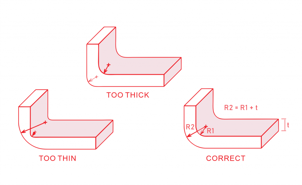
Wall Thickness
Wall thicknessis a very important parameter in plastic injection molding. Maintaining uniform wall thickness generally between 1 to 4 mm allows for an even flow and cooling of the material. This helps to eliminate sink marks, warpage, or excessive shrinkage into the product.
Variations in wall thickness or increasing wall thickness above suggested dimensions can cause unintended dimensional deviations, where tighter process controls need to be implemented to maintain the advertised tolerances.
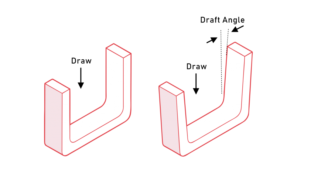
Draft Angle
Draft angles allow a part to be ejected easily from the mold without effects of distortion or stressful alterations. Normally ranging from 1 to 2 degrees, insufficient draft angles can cause distortion, shrinking, and enlargement of parts.
Proper draft angle consideration, albeit slight, is vital to maintaining tight tolerance and smooth production.
You must develop a strong understanding of all these factors to produce molded parts of high quality.
Additional Considerations for Achieving Tight Tolerances
Several additional factors to achieve tight tolerances during injection molding process are:
Material Flow and Injection Pressure
The material flow, depending on injection pressure, melt temperature, and gate design, must be balanced so that the mold fills uniformly in all areas. Uniform flow reduces the possibility of defects and also helps maintain dimensional accuracy.
If the injection pressure settings are too low, filling may not occur completely for more complex part geometry. Hence, pressure settings must not be too high to avoid defects such as flashing or overpacking, which maintain tolerances.
Thermal Expansion and Extreme Temperature Changes
Thermal expansion and contraction will act with plastic materials more especially when there is an extreme temperature change. Therefore, these needs to be taken into consideration while designing in order that the parts stay within acceptable dimensional ranges under operating conditions.
Adopting materials with low thermal expansion coefficients improves dimensional stability.
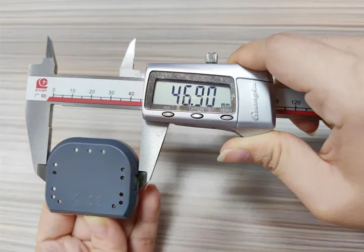
Visual Inspection and Quality Control
Regular visual inspection and advanced metrology, such as coordinate measuring machines, are done for checking whether the molded parts meet the required tolerances. Early detection of deviations through quality control methods with statistical treatment guarantees consistent production quality.
Some defects that are also identified during inspection include sink marks or warpage, which affect dimensional accuracy.
Tolerance Stack and Multiple Components
In multi-component assemblies, tolerance stack can generate misalignment or fit problems. Engineers define tolerance standards for each component to reduce cumulative deviations for proper assembly, especially for systems wherein very tight tolerances ensure precise fit and function.
These factors help in achieveing tight tolerances for improved overall functionality.
Conclusion
Plastic injection molding tolerances are foundational to producing high-precision molded plastic parts that meet the demands of industries requiring reliability and functionality.
As injection molding technology evolves, maintaining high tolerances will continue to drive innovation, enabling the production of complex, high-quality plastic parts for diverse applications.