Injection Molding Draft Angle Guide For Custom Parts

Toys, car components, and numerous other products are made through the injection molding process. Designing a custom part to suit manufacturability involves many factors that the engineers need to incorporate.

Working closely with the design professionals from the onset of the project may help optimize the manufacturing capabilities of custom parts. Injection molding draft angle is one of the early approaches that contribute to optimized custom part production.

A draft is a principle element that must be accounted for in injection molding, a widely renowned rapid manufacturing method. There are other integral components such as ejector pins, wall thickness, parting line, and ribs. However, this guide will concentrate on molding draft angles.

It will specifically delve into the concept of draft angle injection molding and the applicable design guidelines. Read on to see if there are ways you can make your custom part production more effective.

What is a draft angle?

Draft Angle

The draft angle in injection molding is the level of taper included on the features and faces of a custom-molded part. This taper can be shown in terms of mm/mm or degrees. The taper comes in handy during the removal step of the injection molded parts. Without the draft angle, the custom part may not detach cleanly from the injection molding tools.

Why are draft angles important for injection molding?

For a better understanding of the importance of plastic injection molding draft, it is worthwhile to review the basics of this manufacturing process, first. Molten plastic is injected into a mold or cavity to create a part.

Custom part ejection is an essential part of the injection molding process. Before the custom part is ejected, it is in close contact with the mold walls. Like any other interaction between two parts, there are strong contact stresses between the mold and the part. These stresses can be so strong that they can deform the custom part during ejection.

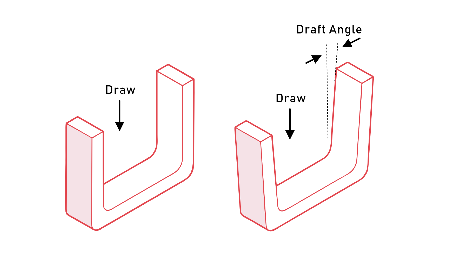
A draft angle is included in the design of the component so that the component can be removed from the mold without excess friction. As soon as the ejection process starts, the surfaces lose contact with each other. Therefore, the contact stresses are eliminated. Without the injection molding draft angle, there would be significant friction that affects the quality of the custom part.

Apart from making the custom part release process easier, draft angles in injection molding minimize the chances of warping. Warping is a serious defect that is characterized by folding. When there is no draft angle, a vacuum may form in the space formed during custom part ejection. The deformation is undesirable because it can affect the functionality and aesthetics of the custom part.

Injection molding draft angles are equally important for the surface finish of the custom part. Since the part doesn’t scratch against the mold wall, the integrity of its surface finish is largely maintained. As long as there is a balance between the draft angle and the surface finish requirements, this need can be met. For custom part surfaces that have protrusions or craters, an adequate draft angle ensures that these features are maintained.

Regarding manufacturing costs, injection molding draft angles can offer huge cost cuts. With draft angles, the custom parts emerge with minimal warps and surface problems. Therefore, the finishing cost for the manufacturer is minimal.

What are the best injection molding materials for draft angle?

Thermosets and thermoplastic material are the best and most common injection molding materials for draft angles. These materials present desirable characteristics for the process.

Several material factors affect the outcome –functionality and quality of the custom part- of an injection molding process. One of them is the shrink rate of the material. This property should be in line with the possible draft angle to minimize the risk of part failure.

Specifically, the best injection molding materials for injection molding draft angles are Polyethylene, Polyvinyl chloride (PVC), Polypropylene (PP), polycarbonate (PC), and nylon. The soft and ductile properties of these materials make it easier for designers to calculate draft angles. Nylon, for instance, can do with zero draft angle.

How does draft angle design affect the surface finish?

The surface finish in injection molding is essential for custom part esthetics and functionality. But the draft angle design can affect surface finish, resulting in any of the many surface finish grades. These surface depth effects are expressed in tabular form in the next section.

Surface Draft Angle Chart for Injection Molding

The surface roughness affects the overall quality of the injection molded custom part. If the draft angle is smaller than required, the surface will be rougher.

Surface roughness in injection molding is characterized by minute valleys and peaks that are usually below 1mm apart. There are different ways of sampling the surface roughness of the injection molded custom part.

Ra, Rz, and VDI

Consequently, there are common parameters including Ra (Arithmetic Mean Deviation) and Rz (ten-point mean roughness) that are related to surface roughness.

There is also the VDI Surface Finish standard, which is the work of a partnership between VDI (Verein Deutscher Ingenieure) and the Society of German Engineers. This standard is now globally recognized and popular with industrial designers and mold designers. The VDI 3400 table covers surface texture grades from #0 to #45.

To achieve various VDI 3400 levels in plastic injection molding part design, specific draft angles are required. Below is a table that uses plastic materials ABS, PA, and PC as examples. Ra and Rz values are also used as references.

Draft Angle (Degrees)

Document
DA-PA DA-PC DA-ABC
0 1 0.5
0.5 1 0.5
0.5 1 0.5
0.5 1 0.5
0.5 1.5 1
1 2 1.5
1.5 2 2
2 3 2.5
2.5 4 3
3 5 4
4 6 5
5 7 6

Surface Texture

Document
VDI Grade Ra Rz
12 0.4 1.5
15 0.4 1.5
18 0.8 3.3
21 1.1 4.7
24 1.6 6.5
27 2.2 10.5
30 3.2 12.5
33 4.5 17.5
36 6.3 24.0
39 9.0 34.0
42 12.5 48.0
45 18.0 69.0

How is the draft angle measured?

Design engineers measure the draft angle as the level of taper of the mold surface in comparison to the mold opening direction. This measurement is in degrees or mm/mm, and can be achieved through various techniques:

  1. Laser scanning

  2. Visual method

  3. Coordinate measuring machines (CMMs)

  4. Sensor technology

  5. Optical Measuring Devices

Laser Scanning

This technique comes in handy for angle measurement where the focus is on accuracy, 3d data, and integration with CAD software. Its non-contact operation suits the inspection of highly intricate custom parts.

Visual Method

While this method risks introducing human errors, it is simple and affordable to use. Experts in the molding process can apply this technique effectively.

Coordinate Measuring Machines

Equally accurate and compatible with CAD, CMM is excellent for traceability. It, therefore, applies best to calculate draft angle where quality assurance and process control are vital.

Sensor Technology

Sensor technology involves the placement of sensors within the mold cavity. Use this technique to achieve real-time feedback, superior process control, and minimal waste.

Optical Measuring Devices

For added versatility and highly accurate measurement of drift angle on straight walls, these devices are applicable. The devices are cameras that have advanced analytics.

Design Guidelines For Draft Angle In Injection Molding

draft angles for injection molding

Injection molding design engineers follow certain guidelines to choose the right draft angle for custom parts. These guidelines are important because no draft angle injection molding is one-size-fits-all.

In other words, the draft angle requirements of one component are most likely different from those of another one. Concerning this, the following design guidelines outlining important design parameters are crucial:

Higher Injection molding degree of draft suits courser surface texture

As we have intimated before, there is a relationship between surface texture and draft angle. The chosen draft angle should be adequate to prevent scrapping off during component ejection. Typically, courser textures go with higher draft angles. This way, the texture level is retained during part ejection.

If you are looking for a mirror finish such as that of polished metal with light texture, half a degree draft angle is enough. When the surface roughness increases by 0.1 mm, there should be a consequent 0.4 degrees increase in draft angle. Sometimes, the draft angle needs to be as much as 10 degrees to achieve a high course texture.

The type of surface features determines the draft angle

advantages of injection molding draft angles

The features on the component’s surface will determine the amount of draft that is necessary. The trick is in adding draft angles if the recessed surface features are deeper. The reason is simple; the deeper the features, the higher the risk of warping. Deeper features present more vacuum during custom part ejection.

To prevent the warping of these parts, higher draft angles are used. As a rule of thumb, an extra few degrees of draft angle degree should go with an extra inch of the part depth. If these parameters are to adjust (based on material type and custom part size), that is only slight.

The draft angle should account for material thermal shrinkage

Custom part geometry and the cooling cycle of the molten resin are related. That’s why the injection molding draft angles can affect the thermal shrinkage of the custom part. Since shrinking typically follows the center of mass of the geometry, internal faces tend to hold onto the mold. Similarly, the external faces tend to separate from the mold.

This phenomenon can affect the dimensions of the custom part. Consequently, this can translate to challenges of the custom part forming the required mechanical fits. The draft angles that the injection molding specialists incorporate must therefore take care of dimensional tolerances related to thermal shrinkage.

If possible, the custom part should have uniform thickness throughout. Variations in thickness mean that the cooling rates also vary. This can result in warping, sink marks, and voids. Although the specific material properties may suggest otherwise, try to keep the thickness within the 1.2mm to 3mm range.

If the walls must be thicker, let it be up to 5mm. Beyond this thickness, the part’s mechanical properties are affected. The production cycle times are also likely to increase.

Sometimes, the custom part must have varying wall thicknesses. That’s where the design experts need to look for ways to make the wall depth transitions gradual. They can achieve this through methods such as vertical surfaces such as fillets and chamfers.

Other Important Design Guidelines for Injection Molding

  • The orientation of the custom part within the mold can determine the amount of draft angle to be used.

  • The selected draft angle should allow for the flawless operation of undercut release systems.

  • Apart from shape and surface features, the weight and dimensions of the custom part also matter. Determine the appropriate draft angle to prevent the sticking of the component during ejection.

  • The design engineer also needs to consider the presence of slides or side actions on the custom part.

Conclusion

Deciding draft angles is a significant step in the product development process. This element should be carefully analyzed and executed for the best injection molding results.

Have you considered the draft angle requirements for your project? Let Aria accompany you on the journey to a superior surface finish for your custom parts.

FAQs

Q1: When should you add draft angles in the design process?

A1: You should add injection molding draft angles in the injection molding design if it is a thermoforming product design. Draft angles may not be necessary when a true negative or female mold is involved. In this case, the custom part detaches from the mold opening the zero draft mold sidewalls due to shrinkage.

The design process requires the addition of draft angles when positive or male molds are involved. This is because the custom part shrinks towards the sidewalls. Since most thermoforming products have both male and female molds, it is customary to add draft angles in the design where these materials are used.

During the cooling stage of the custom part, the positive elements tend to pull the negative elements. This can alter the dimensions of both the cavity and final injection molded parts. Incorporating drafts properly can help minimize this effect, particularly for complex geometries.

Q2: What is the minimum draft angle?

A2: Usually, the draft angle injection molding is about 1.5 degrees. But there are special applications where the draft angle can be anything from 0.5 to 10 degrees, especially where complex part ejection requirements exist.  Typically, incorporating draft of a minimum 0.5 degrees should be the goal for vertical custom part surfaces.

This degree of the draft is a design guideline that can apply when a part requires a nearly uniform angle made on the vertical surface of a part. It is enough of a compromise between the requirements of the injection molding process and custom part designs with straight vertical walls.

Author

Gavin Leo is a technical writer at Aria with 8 years of experience in Engineering, He proficient in machining characteristics and surface finish process of various materials. and participated in the development of more than 100complex injection molding and CNC machining projects. He is passionate about sharing his knowledge and experience.