Have you ever stopped to think about how all the different parts of a machine fit together so perfectly? It’s not by accident, that’s for sure. It’s all thanks to a super important system called Geometric Dimensioning and Tolerancing, or GD&T.
You can think of GD&T as a universal language used among engineers and manufacturers. GD&T is all based on specific symbols and rules, all of which are denoted on the drawings, to show a proper setting of every single feature so that every part is made correctly for the specific application.
GD&T actually takes into account that a pin goes in a hole and that surface A meets surface B at a perfect 90 degrees. In fact, in some cases, it would be impossible to manufacture and build complex items such as cars, phones, etc., without GD&T.
The concept of perpendicularity is one of the foundation elements of this type of language. It is basically one of the cornerstones of designing, and in this material, we will take a look at Perpendicularity in GD&T.
We’ll break down what it is, how it works for different kinds of features, and how it’s different from other controls. We’ll also dive into how you actually measure it to make sure your parts are spot on.
What is Perpendicularity?
So, what is the definition of perpendicularity? Perpendicularity at its core is an orientation control. It is a geometric tolerance that defines how close a feature is to a perfect 90-degree angle, but as with other controls, it is always measured against something else known as a datum feature.
You are not simply saying “this surface needs to be square”; you are saying “this surface needs to be square to this other surface,” which is your reference datum.
The concept is controlling the orientation of a feature, to ensure it presents straight while referencing the base. This is important to ensure that parts fit together properly and function as intended. The perpendicularity requirement is expressed on a drawing with the use of a feature control frame.
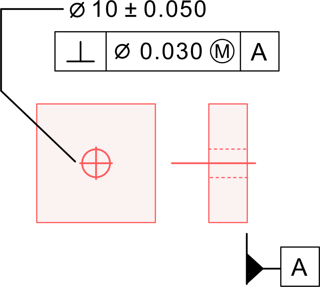
This feature control frame is a small box which contains the perpendicularity feature control symbol (an upside-down T), the allowable tolerance, and the letter that designates the datum feature it is referenced to.
It is a very exacting way of communicating a very important relationship. We are controlling features to be 90 degrees, but we are measuring this relationship in “units of length” and not in degrees.
Surface Perpendicularity
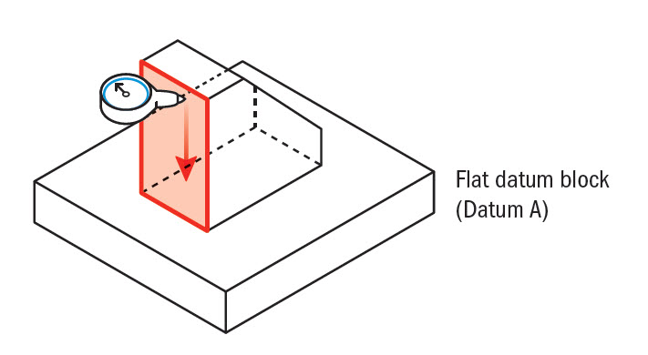
Let’s take this a little further and get into some specifics. There are a couple of ways perpendicularity can be applied. The first way is with surface perpendicularity. This is considered when controlling a flat surface. Let’s consider a simple block. You might want one side of the block to be perpendicular to the bottom surface. The bottom surface is your datum plane.
The perpendicularity requirement referenced on the drawing ensures that the entire referenced surface plane maintains perpendicularity to the datum surface. It is not about just one point or just one line on the surface. It is about the entire surface. Every point on that controlled flat surface has to be within a tolerance.
This is a very widely used application, especially for parts that need to make contact flush against a different part. An easily relatable example is the side of an engine block where another part bolts on to the side. You need that surface to be perpendicular, so there is a proper seal that does not leak.
Axis perpendicularity
The other major type is axis perpendicularity. This is what you will invoke when you have a feature of size, like a pin, a boss, or a hole; instead of controlling a surface, you are controlling the orientation of the feature. So, if you have a pin sticking out of something (a block, for example), you want that pin to be standing straight up, not leaning or tilted to one side.
In this case, the perpendicularity callout is controlling the center axis of the pin feature. It ensures that the axis is perpendicular with respect to the datum plane (the surface the pin is coming out of). This ratio is exceptionally important for assembly fit and purpose. If you have a hole that the pin is supposed to fit into, the axis of the hole must also be controlled.
If you have a pin and a hole, and either the pin or the hole (or both) has a large perpendicularity error, then they will not fit together even if their diameters are both within tolerance size. This sort of control applies to both an external feature (like a pin) and an internal feature (like a hole).
Perpendicularity Tolerance Zone
So, what does GD&T mean by “zone” of acceptable perpendicularity? The perpendicularity tolerance zone is the imaginary boundary within which the controlled feature must lie. The shape of this zone depends on the type of feature you are controlling, which could be a surface or an axis.
Surface perpendicularity tolerance zone
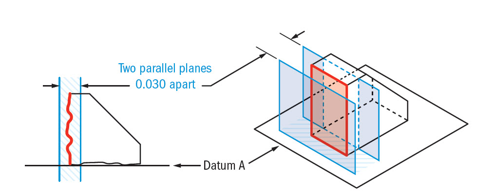
For surface perpendicularity, it is quite simple. You are defining a 3D space bounded by two parallel planes. You can think of it like two flat sheets of glass. These two planes are parallel to each other and also perpendicular to the baseline datum plane. Then the distance between the two parallel planes is the parallelity tolerance that you see in the feature control frame.
Do note that all points on the controlled surface, the entire surface, have to fall within this space. The surface can have ripples or not be perfectly flat, but it only matters that it does not break the zone defined by the two parallel planes acting as boundaries. This is a simple concept, but it is a very powerful way to define the orientation of a surface.
Axis perpendicularity tolerance zone
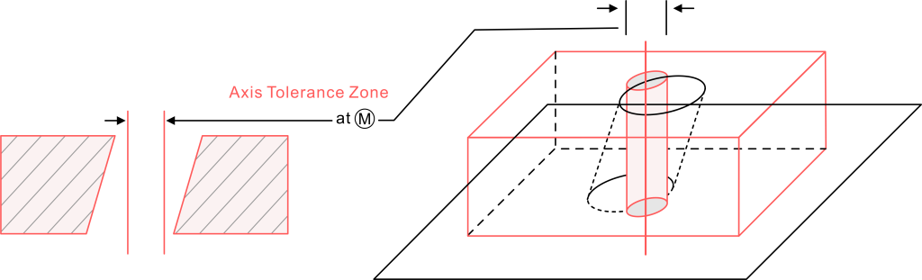
Now, axis perpendicularity, the tolerance is a little different (surprise!). Instead of two parallel planes, it is a cylindrical tolerance zone. It is where the axis of the cylinder is theoretically perfect, parallel to the axis of the primary datum, or is perpendicular to the datum plane. The diameter of the cylinder is the size of the perpendicularity tolerance value from the feature control frame.
The center axis of the actual feature, whether that is a pin or hole, has to fall entirely inside this cylindrical space. So, the pin’s axis may move or tilt a little bit, but as long as it is completely within that imaginary cylinder, it is considered acceptable for perpendicularity. If the perpendicularity callout has a diameter symbol (Ø) in the tolerance section, you would know it is a cylindrical tolerance zone.
Perpendicularity vs Other Callouts
It is very easy to confuse GD&T controls, especially the orientation controls. They all seem to do similar things, but the application is different. Here are a couple of the common things that confuse perpendicularity.
Perpendicularity vs Flatness
This is a big one. Flatness is a form of control. It only has to do with how flat a single surface is and does not reference another feature. Flatness ensures that a surface has no bumps or waves. Perpendicularity does not directly control the flatness of a surface. The surface could be perfectly perpendicular and still be wavy.
That being said, the perpendicularity tolerance indirectly controls flatness. Since the entire surface must fit into two parallel planes, it cannot be bigger than the perpendicularity tolerance. For example, if you have a perpendicularity tolerance of 0.1, then the flatness of that surface cannot be larger than 0.1. This is an example of one control refining another.
Perpendicularity vs. Angularity
This may seem straightforward, but there are a lot of subtleties here. While angularity is an orientation control that establishes a tolerance zone for a feature at any angle from a datum, it is important to note that the angle does not have to be 90° (perpendicular). So really, you can say that perpendicularity is just a special instance of angularity where the angle is 90°.
And this is true! You can technically utilize an angularity with a basic angle of 90° to create a perpendicularity control. Although the intention is the same, standard practice is to utilize the dedicated perpendicularity symbol, and it will communicate the correct angle of 90° to anyone looking at the drawing. Using the correct gd t symbol for the job will help eliminate any possible confusion.
How To Measure Perpendicularity
Alright, you have a part that has a perpendicularity callout. How do you check it? The method for checking a perpendicularity is based on whether you are measuring the surface or the axis, and what tools you have readily available.
Measuring surface perpendicularity
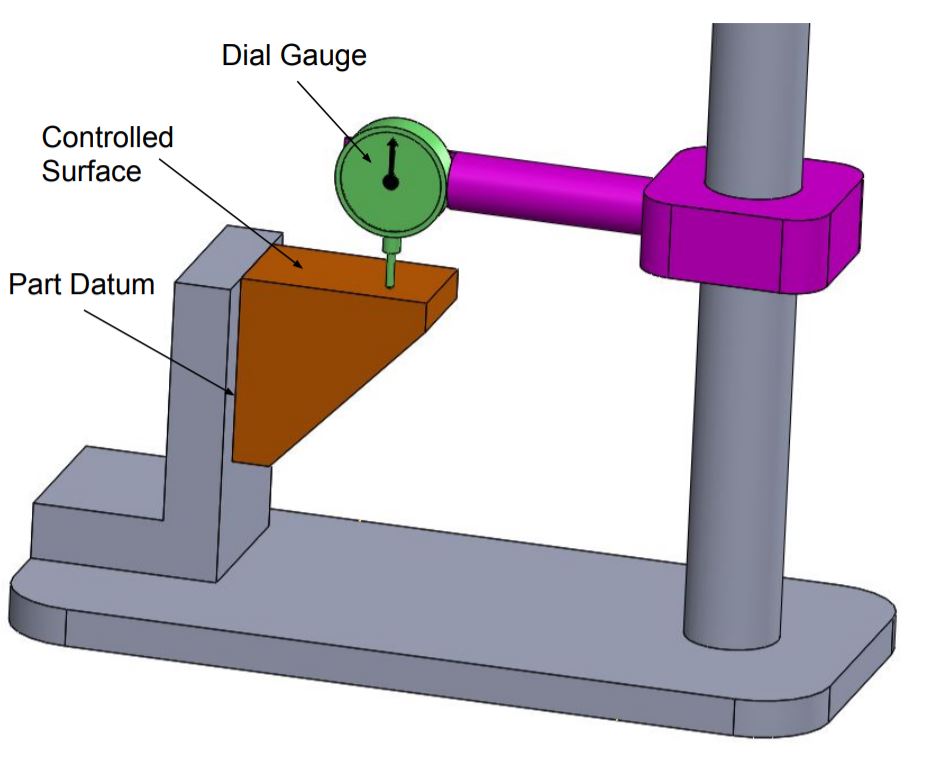
There are a few different ways to measure surface perpendicularity. The classic way is with a granite surface plate, height gauge, and dial indicator. In this instance, you would place the datum surface of the part flat on the surface plate. Next, you would run the height gauge’s dial indicator across the surface you are checking (but you could also measure the surface being checked with an independent dial indicator).
You would sweep the indicator over the one surface plane and pick out the highest and lowest readings. The difference between these readings is the total perpendicularity error. If that value meets the allowable tolerance, then the part passes. This is an easy example of a manual check. A CMM (Coordinate Measuring Machine) will do this method so much faster and better, by touching hundreds of points on the surface.
Axis perpendicularity measurement
In measuring axis perpendicularity, it is slightly more complicated. For an external feature like a pin, you could lay the part down with its datum plane on a surface plate and then use a dial indicator to measure the runout at two separate heights along the pin while you rotate the part. Then the difference in runout can be used to calculate the tilt of the axis.
However, for an internal feature like a hole, it becomes more difficult. This is an example where you would want to use a functional gauge. A functional gauge is a physical, actually existing tool that represents the worst-case mating part. For a hole, it would be a pin whose diameter is equal to the smallest size of the hole minus the perpendicularity tolerance.
If this gauge pin can go completely into the hole while its datum on the part is resting on the plate, then the part passes. This method is extremely useful because it checks size and orientation together, and it could make gauging on the shop floor super easy. Utilizing maximum material condition can also provide a bonus tolerance, making it a little easier when you think of manufacturing.
Perpendicularity In CNC and 3D Printing
In the context of creating parts using any method, you will be thinking every day of achieving good perpendicularity.
For CNC machining, the squareness of the machine is very important. More specifically, the z-axis must be perpendicular to the x-y plane. The smallest error in squareness and alignment within the machine will end up inducing error in the parts that are created, and there are a number of things to consider in manufacturing, which if not considered can lead to a perpendicularity error, e.g., tool deflection, clamping, material stresses, etc.
The challenge of achieving perpendicularity is a little different in the realm of 3D printing. For FDM printers, the gantry motion along the Z axis must be perpendicular to the build plate. If not, you will have skewed or leaning parts. Layer shifting of prints can also lead to features that do not add to perpendicularity correctly.
In regard to resin printers, you would need to properly calibrate the machine, and the build plate must be levelled. In any case, achieving the tight tolerances of producing parts to a GD&T callout of Perpendicularity is not typically easy in any technology, particularly if no post-processing is used.
In many cases, these critical surfaces or holes are machined after printing and before the parts are completed to ensure the tight tolerances of perpendicularity.
Conclusion
So, there you have it; perpendicularity really is a huge deal in manufacturing and engineering. It is one of the most fundamental and well-known orientation control tools in GD&T.
We have spoken about what perpendicularity is, from surface perpendicularity, to how to control the perpendicularity of axes with the use of holes and standing pins.
We have also discussed the perpendicularity tolerance zone, which contains two parallel planes, a two-dimensional perpendicularity zone, or a cylindrical tolerance zone, which establishes the tolerance for acceptable limits of variation.
So then, it is vitally important to understand, in regard to a picture, how to apply the perpendicularity callout, how to measure it, and how the perpendicularity is different than other types of controls.
This is a crucial piece of the puzzle that helps make sure parts not only look right, but fit and function right every time parts are demanded. Perpendicularity is an important piece of Perpendicularity in GD&T.
FAQs
Q: What is the difference between perpendicularity and parallelism?
A: Perpendicularity is an orientation control that tells you that a feature is 90 degrees to a datum feature. Parallelism is another orientation control that tells you a feature is at an angle of 0 degrees, that is parallel, to a datum. One control tells you squareness, the other, being parallel.
Q: Can perpendicularity be applied to a hole pattern?
A: Yes, you can absolutely use a perpendicularity control on a pattern of holes. In this specific instance, perpendicularity tolerance would be applied to each specific axis in the hole pattern to ensure that each and every hole is drilled perpendicular to the datum surface, critical for bolt assemblies.
Q: Does perpendicularity need a datum?
A: Yes, perpendicularity will always require a datum feature. It is an orientation control and means that it describes the relationship between two or more features. You cannot define something as perpendicular if you do not have a datum reference to be perpendicular. It can reference a primary datum, a secondary datum, tertiary datum.
Q: How is perpendicularity measured in the field without the use of a CMM?
A: For a flat surface, you can utilize a precision square and feeler gauges against a flat surface plate that is known to be flat. For an axis, you can use a dial indicator and a height gauge to check if the surface is tilted. A custom-made functional gauge is also a very effective and quick way to check on the shop floor.
Q: What happens when I exceed the toleranced perpendicularity?
A: When you exceed the toleranced perpendicularity, it is considered non-conforming. This usually leads to assembly problems, and parts do not fit together, leading to gaps. Furthermore, it can affect the function of the part, such as excessive wear, poor sealing, or even catastrophic failure. This is a significant perpendicularity error.