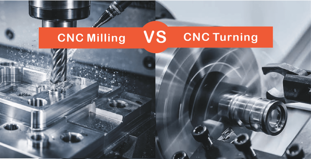
CNC Milling vs CNC Turning: Key Differences and How to Choose

cnc turning Vs CNC milling

Share:

Table of Content

Table of Content

CNC milling and CNC turning both cut material away from a solid workpiece using computer-controlled toolpaths. Both hold tight tolerances. Both run aluminum, steel, titanium, and engineering plastics. But they work in opposite ways, and choosing the wrong one costs you time and money before the first chip hits the floor.

The one-sentence rule: in turning, the workpiece spins; in milling, the cutting tool spins. That single mechanical difference shapes everything else: which geometries each process can make, what tolerances it holds naturally, how fast it runs, and what it costs per part.

This guide walks through both processes in detail, compares them across every dimension that actually matters to a buyer or engineer, and gives you a clear decision framework for your next project.

Key Takeaways

Before getting into the details, here’s a reference table covering the key parameters:

Feature CNC Milling CNC Turning
What moves Cutting tool rotates Workpiece rotates
Axes 3–5+ axes (X, Y, Z + rotary) 2–4 axes (X, Z primary)
Best geometry Prismatic, pockets, flat surfaces Cylindrical, conical, symmetric parts
Standard tolerance ±0.127 mm ±0.025 mm
Precision tolerance ±0.02 mm ±0.013 mm on diameter
Surface finish (Ra) 0.8–3.2 μm standard 0.4–1.6 μm standard
Cost per hour $40–$200/hr (3-axis to 5-axis) $30–$100/hr
Setup complexity Higher — multiple fixtures often needed Lower for standard round parts
Cycle time Longer for simple round features Faster for cylindrical high-volume runs
Chip formation Intermittent cut per flute Near-continuous cut
Heat behavior Tool cools between flute contacts Continuous heat buildup at insert
Automation Pallet systems, robotic loading Bar feeder enables lights-out
Typical parts Brackets, housings, molds, manifolds Shafts, bushings, fasteners, fittings

What Is CNC Milling?

CNC Milling Service​

CNC milling is a subtractive process where a rotating, multi-point cutter removes material from a workpiece clamped to the machine table. The spindle moves across X, Y, and Z axes, carving out the programmed geometry while the workpiece stays fixed.

Milling is the go-to process for prismatic parts: flat faces, pockets, slots, angled surfaces, geometry across multiple faces. If the part isn’t rotationally symmetric, it’s a milling job.

Types of CNC Milling

5-Axis Milling Machines

3-Axis Milling. The most common setup: cutter moves in X, Y, and Z. Works well for parts with features on one or two faces — brackets, plates, enclosures, covers. Most job shops run 3-axis as their core business.

4-Axis Milling. Adds a rotational A-axis (rotation around X). You can machine features on the side of a part without re-clamping. Useful for cylindrical parts that also need milled flats, slots, or cross-holes.

5-Axis Milling. The tool and table tilt and rotate simultaneously. Compound angles and complex curved surfaces in a single setup — work that would otherwise need four or five separate fixturings on a 3-axis machine. Standard in aerospace and medical implant production.

Common Milling Operations

  • Face milling: Creates flat, smooth reference surfaces
  • End milling: Cuts slots, pockets, and profiles
  • Thread milling: Produces threads with a helical toolpath — more flexible than tapping for difficult materials
  • Slot milling: Cuts keyways and precision grooves for drive shaft assemblies and alignment features

What Is CNC Turning?

Online CNC Turning Services​

In CNC turning, the workpiece spins on a lathe spindle at programmed RPM while a stationary cutting tool moves in to remove material. The insert stays in near-continuous contact with the rotating surface throughout the pass.

The result is parts with rotational symmetry: shafts, cylinders, cones, discs, bushings, fittings, pins. Spin the finished part 360° around its central axis and it looks identical at every angle. If that describes your part, it belongs on a lathe.

Types of CNC Turning

2-Axis CNC Lathe (Standard).

X-axis for cross-slide movement, Z-axis for longitudinal travel. Handles OD turning, facing, boring, and threading. The right tool for high-volume simple shafts, pins, and bushings where cycle time is everything.

Turn-Mill Center (Multi-Axis with Live Tooling).

A live milling spindle on the turret lets you drill cross-holes, cut keyways, and mill flats without moving the part to a separate machine. We use this regularly for hydraulic valve spools and actuator shafts: one setup, complete part, better concentricity.

Swiss-Type CNC Turning.

Bar stock feeds through a guide bushing; tools cut very close to the support point. Near-zero overhang eliminates deflection on long, slender parts. Watch components, medical bone screws, catheter fittings, and micro pins are typical Swiss work. Tolerances down to ±0.005 mm are achievable on diameters under 32 mm.

Common Turning Operations

  • OD Turning: Reducing outer diameter to the target dimension
  • Boring: Enlarging and finishing internal diameters
  • Grooving / Parting: Cutting recesses or separating finished parts from bar stock
  • Threading: Single-point thread cutting for precision fits — more accurate than die threading for tight-tolerance assemblies

CNC Milling vs CNC Turning: Detailed Comparison

1. Part Geometry

Geometry is the single biggest factor in process selection. It eliminates 80% of the decision before you look at anything else.

CNC turning is built for rotational symmetry. If the part looks the same at every angle when you spin it around its central axis, it goes on the lathe: shafts, bushings, threaded fittings, cylindrical pins.

CNC milling handles everything else. Prismatic parts with flat faces, deep pockets, angled features, or geometry on multiple faces require a mill. An engine housing, a bracket with a bolt hole pattern, a mold cavity. Turning simply cannot make these geometries, and there is no workaround.

The grey zone is parts that are primarily round but also need cross-holes, keyways, or milled hex flats. A turn-mill center handles these in one setup. Two separate operations means paying twice for setup, handling risk, and potential datum errors.

2. Tolerances

This is where engineers often get the choice wrong by applying milling tolerances to turning and vice versa.

Turning excels at diameter tolerances and concentricity. On a well-maintained lathe, holding ±0.013 mm on a shaft OD is routine,  it’s a natural output of the process. Concentricity and roundness come essentially for free when the part rotates around a fixed axis.

Milling excels at positional tolerances between features. Hole pattern locations, perpendicularity between faces, complex GD&T callouts across a prismatic part — these are where milling with proper fixturing and CMM verification shines.

The practical rule: single diameter or bore → lathe. Positional accuracy across a complex part → mill. Applying the wrong process to your tightest tolerance is the most expensive mistake you can make at the quoting stage.

3. Surface Finish

Turned surfaces show concentric spiral marks from the insert. At fine feeds with the right nose radius, you can reach Ra 0.4 µm without secondary finishing, smooth enough for bearing seats and hydraulic sealing surfaces.

Milled surfaces show overlapping arc patterns from the rotating cutter path. A face mill on aluminum reliably reaches Ra 0.8 µm. Ball-nose finishing passes on 3D contours typically land around Ra 1.6 µm.

For cylindrical functional surfaces like bearing journals and seals, turning gets you there faster and at lower cost. For flat faces and cosmetic housings, face milling is the better tool.

4. Cutting Mechanism and Heat

In milling, each flute contacts the workpiece briefly before clearing. That short break lets the tool cool between contacts, which is why milling is generally gentler on inserts when working tough materials like stainless steel or titanium. Chips are short and manageable.

In turning, the carbide insert stays in near-continuous contact with the spinning workpiece throughout the entire pass. Heat builds steadily at the cutting edge. For aluminum this is not a problem. For stainless and titanium, insert grade selection, cutting speed, and coolant flow all need more careful attention. The margin for error is narrower.

5. Setup and Cycle Time

Turning setup is fast. For a standard shaft, chucking the bar, setting offsets, and taking a test cut takes 20 to 30 minutes. The insert is cutting throughout the pass, so cycle times are short. A shaft that takes 3 minutes to turn from bar stock might take 25 to 40 minutes to mill from square billet.

Milling setup takes longer. Fixturing the workpiece, setting work coordinates, loading multiple tools, running a dry cycle: all of this happens before the first chip. A complex milling job with three or four setups can take 2 to 4 hours just to prepare. For small batches, that setup cost per part is real. For large batches, it spreads out and becomes less significant.

6. Cost Per Part

Turning is cheaper per hour and faster per part for round geometry. A standard 2-axis lathe in contract manufacturing typically runs $30 to $50/hr. A 3-axis mill runs $40 to $80/hr, and 5-axis runs $80 to $200/hr depending on market.

The hourly rate is only part of the picture. What matters is cost per part: machine time plus setup amortized over batch, plus tooling, material, and finishing. For the hydraulic fittings example at the top of this article, moving from milling to turning cut per-piece cost by over 90%, driven primarily by faster cycle time and simpler setup.

For complex prismatic parts, the cost comparison becomes irrelevant. Milling is the only process that can make the part.

7. Material Waste

In milling, you typically start with a rectangular billet and remove a large percentage of it. For a titanium aerospace bracket, the raw billet can weigh 80 to 90% more than the finished part. That scrap either recycles at a fraction of its original value or gets discarded.

In turning, starting from round bar stock means you begin close to the finished geometry. The buy-to-fly ratio is better and material cost per part is lower. The exception is when a turned part needs a large-diameter feature at only one end, forcing you to buy oversized bar stock for the entire length.

8. Automation

CNC turning with a bar feeder is one of the most automation-friendly setups in manufacturing. Load a bar, start the program, and the machine runs unattended through the entire bar, cycling through parts automatically. This is why high-volume fasteners, fittings, and connector bodies are almost always turned parts. Lights-out production is straightforward.

CNC milling automation requires robotic loading systems or pallet changers to fixture each part. These setups are common in high-volume automotive cells but require significant upfront capital. For lower-volume milling work, operators load and unload between cycles.

How to Choose

Getting the process wrong early locks in a cost problem that follows you through the entire production run. Work through these five steps before your design is frozen.

Step 1: Start With Geometry

The shape tells you 80% of what you need to know. Rotationally symmetric? Lathe. Prismatic, blocky, or features on multiple faces? Mill. When in doubt, look at the raw stock: round bar stock means turning, plate or billet means milling.

Step 2: Identify Your Tightest Tolerance and Match It to the Right Process

Shaft OD, bearing bore, sealing surface on a diameter → CNC turning. Hole pattern position, flatness, perpendicularity between faces → CNC milling. Identify the most critical dimension first, then choose the process that achieves it most reliably.

Step 3: Count Your Setups

Every re-clamp adds time and risk of datum error. At the design stage, group features so they’re accessible from as few orientations as possible. Two setups is a reasonable target for most milling jobs. If your design requires four or more, revisit the geometry before releasing drawings.

Step 4: Match Volume to Process Economics

Under 20 pieces: milling is more flexible; setup cost per part matters less.

20–500 pieces: geometry drives the decision more than volume.

500+ pieces of round parts: turning with a bar feeder is almost always the lowest cost option. Setup cost becomes negligible per part; labor cost drops to near zero with lights-out running.

Step 5: Run a Quick DFM Check

70–80% of manufacturing cost is locked in at design. A few checks that consistently save money:

  • Round it if you can. Cylindrical features are faster and cheaper to turn than to mill from billet.
  • Keep internal corner radii generous. Tight corners in pockets require small tools, slow feeds, and more passes.
  • Avoid deep narrow pockets. Keep depth below four times pocket width where possible.
  • Standardize threads and holes. Non-standard sizes need special tooling and add lead time.
  • Don’t over-tolerance. Every callout tighter than ±0.05 mm adds inspection, slows the machine, and raises cost.

Conclusion

Most process selection mistakes fall into two categories: milling a part that should be turned, and holding a tolerance tighter than the application needs.

Get the process right for your geometry first. Think about production volume before locking the design. And don’t let a supplier’s available equipment make the process decision for you. That’s how you end up paying 5-axis milling rates for a shaft that belongs on a lathe.

If you’re not sure which process fits your design, send the drawing for Aria review. The geometry usually makes the answer obvious within seconds.

Written By

Gavin is a manufacturing specialist and content editor at Aria Manufacturing. With years of experience in CNC machining and mechanical design, he helps global clients choose the right manufacturing solutions and improve part performance while reducing costs.

CNC milled aluminum precision part with complex geometry and multiple machining features

Custom Quality Parts By Aria

Send your specs. We’ll get back with a quote in 12 hours.

Scroll to Top