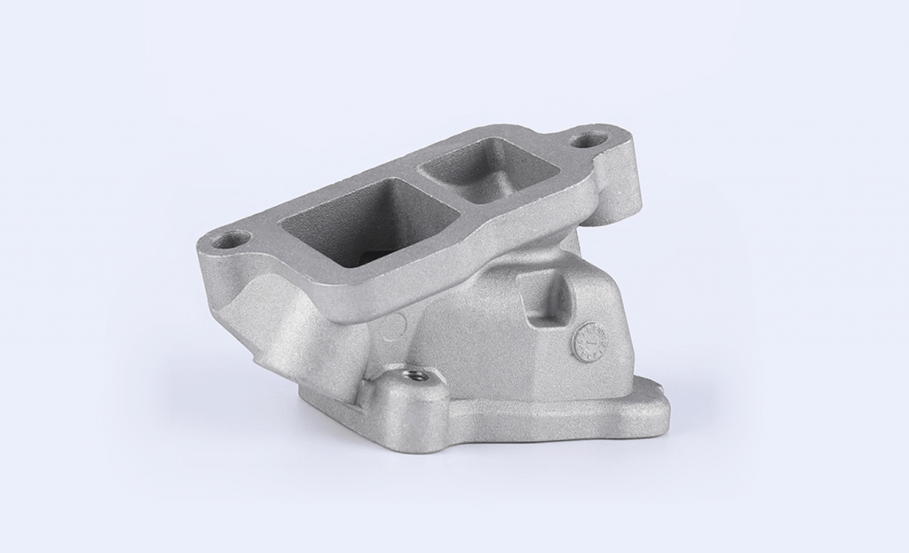
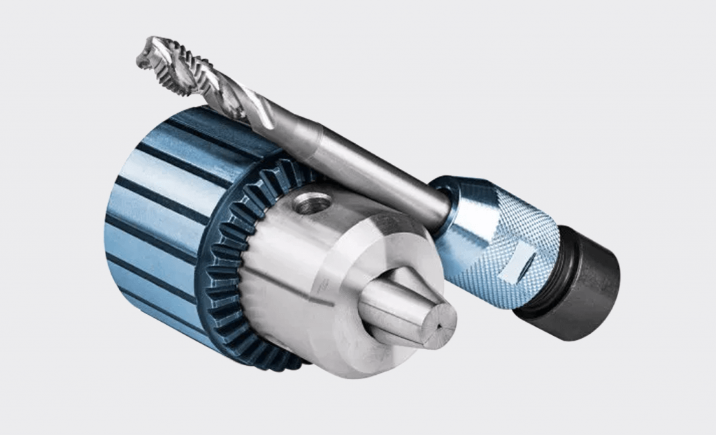
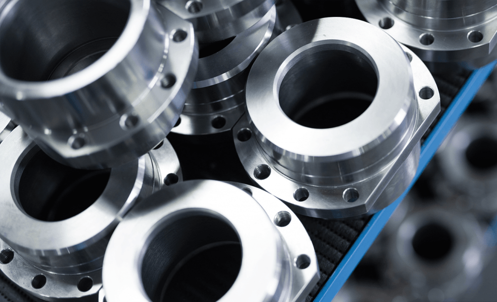
When developing a new product, there is always a need to make a prototype of the designed part or system before funding large amounts of production facilities or Assembly line. The main reason for this need is the high cost and time-consuming preparation of production tools. Therefore, prototyping is necessary for troubleshooting and design evaluation before a complex system is ready for production and market.
One process that helps manufacturers accelerate product development is Rapid Prototyping (RP).
Rapid prototyping is the process of prototyping a product that gives manufacturers a quick look at the final product.
Rapid Prototyping Technology
Rapid prototyping is a technology that automates prototyping thanks to the CAD process with “holographic printers” that allow designers to quickly create tangible prototypes, communicating their design ideas to workers or customers. In addition, rapid prototyping is also used to test new products.
Because it takes less time, RP helps manufacturers quickly bring products to market and reduce production costs. That is also a prominent advantage of rapid prototyping. Rapid prototyping technology began in the mid 80’s. The characteristics of rapid prototyping are:
- Performing prototyping in a very short time, this is the strength of this method.
- The product of rapid prototyping can be used to test samples produced by other methods.
- The generated pattern can support the production process
The development of Rapid Prototyping (RP) is closely related to the development of industrial applications of computers. The reduction in the cost of computers, especially personal computers and minicomputers, has changed the way factories work in factories.
The increased use of computers has spurred progress in many computer-related fields including design (CAD–Computer Aided Design), manufacturing (CAM–Computer Aided Manufacturing), numerical control machining through computer (CNC – Computer Numerical Control). Specifically, the emergence of the RP system could not be without the presence of CAD.
The foundation of rapid prototyping
2.1/ A model or a detailed part designed on a CAD/CAM system
Samples must show full physical properties as real products shown by closed curved surfaces with clearly limited dimensions. That is, the internal and external data and also the limited scope of the sample must be defined. This requirement is not really necessary for the solid model. The cubic model will automatically limit the volume. This requirement ensures that all cross-sections are closed curves to create the solid.
2.2/ The solid model or the surface model is converted to “. STL”
“STL” (Stereo Lithography) are data files that are the starting point of 3D systems. The .STL file approximates surfaces as polygons. High-order surfaces have to use a lot of polygons, which means that the .STL files used for surface details must be very large. However, there are some rapid prototyping systems that only accept .IGES (Initial Graphics Exchange Specification) data to provide exact properties.
2.3/ The computer parses the .STL . file
This analysis is to clearly define the pattern for production and the thin layers on the cross-section. The cross-section is created by descending during solidification of a liquid or powder and then incorporated into a 3D model. Another possibility is that the cross-sectional surface could be thin layers or in bulk, thin layers that can be bonded together to form a 3D pattern. In other words, the evolution of rapid prototyping is represented by four basic aspects: input, rapid prototyping, materials, and applications.
Input data
The supplied 3D data is transmitted by electronic signals as required to describe problems related to the object. It is possible to start from the following two types of models: a computer model or an object model. The CAD system generated the model on the computer in either face or solid form.
On the other hand, not all patterns from the object are obvious. Its data is obtained by a method called reverse engineering. In reverse engineering, equipment such as coordinate measuring machines and laser markers can be used.
Rapid prototyping method
Depending on the processing method of the manufacturer, we can analyze it into a number of forms such as: photo-curing, cutting and gluing/joining, melting and solidifying. (Melting and Solidifying/Fusing)… The photochemical treatment can also be analyzed into small groups: single laser beam, double laser beam and plating lamp.
Material
Depending on the characteristics of the material, we can choose the material: block, liquid or powder.
In the form of blocks can have different forms such as pellets, wires or sheets. Some materials are currently used such as: paper, nylon, plastic, wax, metal and ceramic, etc.
Try Made by Aria Now
All information and uploads are secure and confidential.
Applications of Rapid Prototyping
Almost all products created using rapid prototyping need to be tweaked or refinished before being put to use. Applications can be grouped into: Design, engineering analysis and planning, tooling, and manufacturing.
Rapid prototyping technology has brought huge profits in areas such as products of the following industries: mechanical engineering, aerospace, automotive, biomedical, electrical-electronics, leather and footwear industry, fashion, etc. jewelry, consumer products, etc.
Advantages and disadvantages of rapid prototyping technology

3.1/ Advantages
Process improvement because:
- Design iteration reduces time and hard-to-detect problems.
- Pre-check the assembly and modify the sample.
- Pre-stress test and product strength.
Improve product quality because:
- Easy to plan ahead.
- Difficult problems are eliminated during the design-manufacturing phase.
- Visualize the product better than the drawing.
Improve productivity because:
- Correct errors before entering the production line or production cell
- Mold has high thermal conductivity
- Mold cooling water channels are made in the RP . machine
Market improvement because:
- Products get to market sooner and more reliably
- Predict market demand more realistically
- Documents and materials are prepared in advance
3.2/ Disadvantages
- High price
- Currently, it is not possible to directly produce metal molds
- Low precision, low physical characteristics
- The metal molecular density after machining is low, the surface gloss is not high
- Unmeasured product stress, limited elasticity.
3.3/ The benefits and risks of Rapid Prototyping
Rapid prototyping and rapid tools bring huge profits to both designers, manufacturers, buyers and users of the product. However, the risks brought by it are also very high because this technique is still under research and development.
3.4/ Compare the methods of rapid prototyping
The characteristics of rapid prototyping methods: SLA , SLS , LOM , FDM , SGC , Actua can be illustrated in the following table:
| SLA 250 | SLS 2000 | LOM 1015 | FDM 1600 | SGC 4600 | Actua 2100 |
| 195000 | 397000 | 95000 | 110000 | 295000 | 65000 |
| 36000 | 68000 | 17000 | 7000 | 30000 | 7000 |
| 0.1 | 0.05 - 0.38 | 0.07 - 0.5 | 0.05 - 0.76 | 0.06 | 0.05 |
| 0.05 | 0.127 | 0.254 | 0.127 | 0.5 | 300 dpi |
| 25x25x25 | 30Dx38H | 28x35x36 | 68x86x92 | 35x35x35 | 25x20x20 |
| .stl, .slc | .stl | .stl | .stl | .stl | .stl |
| Maestro | Projectary | LOM slice | Quick Slide | DFE | Allegro |
| Laser HeCd | Laser CO₂ | Laser CO₂ | Nhiet | Luu hoa | Nhiet |
| 13138 | 26867 | 11148 | 16102 | ||
| 5652 - 8156 | 6002 - 14911 | 11148 | 16102 |
Try Made by Aria Now
All information and uploads are secure and confidential.
Features of rapid prototyping methods
Conclusion on rapid prototyping
- If you compare the average size, the Thermojet device is the cheapest and the SLS unit is the most expensive
- The highest achieved accuracy is SLA, the lowest is SGC
- Through the above comparison table, when manufacturing the same part on different machines, we find that the cost for the part processed by SLA technology is the lowest, the highest is SLS on the same number of criteria and parameters technique posed.
- In general, we can see that if the investment costs as well as the advantages and disadvantages are taken into account, SLA technology has many advantages and is widely used in 2115 devices, accounting for 31% of the world.
3D modeling methods
Thanks to 3D rapid prototyping, everything is now simplified. A few methods of this rapid prototyping technology:
- Stereo Lithography Apparatus (SLA): This technology is based on the basic principle of using a laser beam to shine on a photosensitive rubber epoxy liquid bath in the cross-section of the sample and due to the polymerization phenomenon under the action of the beam. The laser solidifies this liquid layer forming a layer of the specimen. Advantages of this method:
- The system is solid and fully automatic
- High dimensional accuracy +/-0.1 mm
- High surface gloss
- High resolution suitable for complex details.
Enables quick and precise metal forming

Laminated Object Manufacture (LOM): This method is suitable for large-sized specimens, this method uses a CO2 laser to cut thin sheet materials along the contours of the cross-sections of the sample, then temperature is used. Melt glue on the surface of the sheet to glue the sections together.
Selective Laser Sintering (SLS) rapid prototyping technology: based on the principle that the laser beam solidifies the powder material within the boundary of the section. Make them stick together where there are surfaces in contact with the laser. This technology is applicable to most materials with high ductility.
Fused Deposition Modeling (FDM): in this technology, the molten material is extruded from a CNC-controlled injection molding head to create a section of the sample.
3D Printing (3DP): 3D Printing technology uses powdered materials to make samples, especially it does not use heat sources to create physical and chemical changes or melt materials, but uses a type of adhesive sprayed on it powder layer to create adhesion between powder particles and between layers.
All of this leads rapid prototyping to a future where all products are made with 3d printers. You just need to come up with an idea, the rest let the technology of the future – rapid prototyping technology turns all your ideas into reality.
Try Made by Aria Now
All information and uploads are secure and confidential.
Prototyping and CNC design
CNC machines are nothing without some of the prior processes required to program them. I’m referring to CNC prototyping and design to establish what you want to achieve with the machining process. To do this, CAD/CAM software is often used to design what is to be manufactured or modeled and then converts the model into an understandable code for the CNC machine so it can interpret the movements that it has to do.
To design applicable to CNC machines, a series of processes and software are required:
Measuring tool: to perform the entire measurement process necessary to create a proper design. For example, if you want to make a gear for a motor, it must have the same characteristics of teeth, diameter, etc., so that it can engage and operate correctly.
CAD software: Designers will use these programs to draw pieces on the computer as they would be expected in reality, in 2D, 2.5D, or 3D. The differences between these three types of designs are:
2D: in two dimensions (flat), such as CNC cutting sheet metal.
2.5D: you work with two and a half dimensions, which show that you can do the same thing in 2D, but you can also work with layer thicknesses. For example, a laser engraving.
3D: you work with three dimensions, can create shapes with volume. For example, when spinning a piece.
Simulation software
Sometimes when it comes to mass production or critical parts, simulation software is often used to ensure the results you want:
It could be the software that reads the G-Code generated and can predict problems that may arise during machining so that they can be rectified in advance. In this case, simulation will be performed after stage 4.
It can be a piece of software that simulates the mechanism or how the parts are used to see if they are in good working order, possible failures during operation, reliability, etc. In this case, simulation will be performed before CAM (phase 4).
CAM software: thanks to this type of program, the user will be able to easily convert the CAD design to G-Code this is understandable by the CNC machine, as is the case with 3D printers. On the other hand, some CAM packages also include additional tools for calculating feeds and speeds that will occur on the CNC machine. Two things to note at this point:
CAM is CNC “alternative” to Cutter in 3D printing or additive manufacturing. Slicers He is in charge of taking the 3D CAD design and cutting it or dividing it into layers so that the machine can generate it through the extruder or expose the plastic.
CAM is not oriented to additive manufacturing in this case, but to subtractive manufacturing. In other words, layers will not be added, but from an original piece or block, material will be removed until the final shape is reached. For example, imagine a CNC router working with a block of wood to create an ornament for a piece of furniture. In that case, from a square block of wood, the machine will use the appropriate tool or cutter to carve the designs and remove the unnecessary parts.
Control Software in CNC Machining
control software: it is a program that is integrated into the CNC machine itself, because the upper part is in the computer used for the design, it will be in charge of reading the G-Code file that has been transferred to the machine and will convert it into The control signals of the machine’s motors to perform the necessary movements for the part machining are described.
CNC machine: It will be in charge of processing the work so that the result is equal to the design that was created initially. For example, if you have designed a logo and want to laser engrave on the plate, and then the laser head will make the necessary movements to engrave the correct shape.
QA: In some cases, especially for mass production, an extra step of part quality checking will also be needed, which can be automated or manual. In many cases it is based on randomly selecting a part or a batch and performing tests to see if it meets expectations, standards, etc.
As you can see, both 3D Printers like CNC machines have similar process. In fact, a 3D printer can be thought of as a CNC machine for additive manufacturing.
Try Made by Aria Now
All information and uploads are secure and confidential.
Categories
Share On
Recent Post

A Complete Guide on the Passivation of Stainless Steel
Have you ever thought about why stainless steel looks so

3D Printing Vs Injection Molding
Preparing for production is a crucial moment for any company.


