To improve product quality, reduce cost, shorten the development cycle, formulate several advanced manufacturing development strategies and plans, adjust the industrial structure, promote industrial transformation, urgent need to use intelligent manufacturing to enhance capacity and efficiency. CNC manufacturing is the upgrading process of intelligent manufacturing. The most intuitive advantage is that CNC manufacturing can process more complex products, such as high-end products mobile phone (computer) back shell in the size of a few inches in the range of round hole, square hole, screw hole, phone card slot, camera slot, and other large hole slot position.
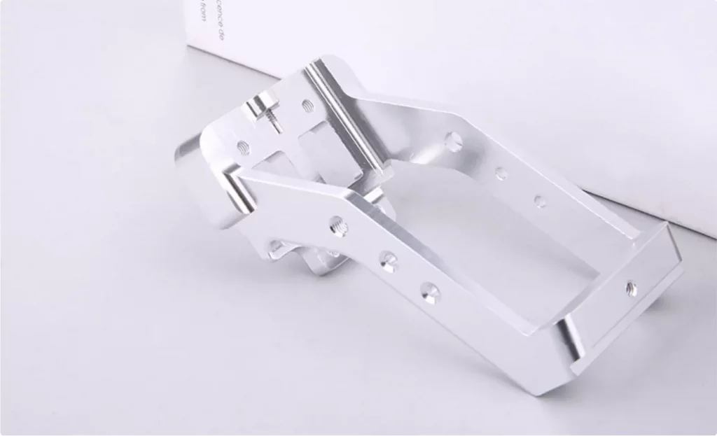
The structural shape of each part is different, and the technical requirements of each side are additional. You want to perform secondary processing on an existing part, such as cutting, slotting, drilling, or cutting bevel. Because zero is irregular, how do I get it to work in the right place?
(1) In the parts, as far as possible to choose the design standard as the position standard
Choosing the design datum as the position of the positioning datum can prevent the positioning error caused by the mismatching datum, ensure the machining accuracy and simplify the programming. Ensure the realization of technical design requirements and accurate, reliable, and convenient clamping.
When making a machining plan for a part, the best finishing conditions are first selected according to the principle of conforming to conditions to specify the part’s machining path. Therefore, the machined surface must be considered a rough standard during initial machining.
(2) When the positioning datum and design datum of parts do not match, and the processing surface and design datum are not processed simultaneously in an installation, the drawings of parts must be carefully analyzed to determine the design function of the design datum of parts. By calculating the dimension chain, the tolerance range between positioning datum and design datum is strictly defined to ensure machining accuracy.
(3) Suppose the CNC milling services can not complete the entire surface processing simultaneously, including the design reference. In that case, it should be considered that the selected reference can be used for positioning, and then all the major precision parts can be processed at one time.
- (4) The selection of positioning standards should ensure the completion of as much processing content as possible. To this end, we must consider the positioning method that a single surface can be machined. As far as possible, select the machined surface’s design (process) datum as the good datum. For non-rotating parts, it is best to use a positioning scheme with one and two holes so that the tool can process another surface. Machining holes can be added and placed if the workpiece does not have suitable holes.
- (5) In the batch processing process, the position reference of parts should be as far as possible with the workpiece coordinate system matching tool reference (after processing, the workpiece coordinate system origin and position reference between the size value).
During batch processing, fixtures are used to position and install the workpiece. The toolsets up the artifact coordinate system one at a time and then processes a series of artifacts. If the tool reference of the workpiece coordinate system matches the positioning reference of the part, the positioning reference can be transferred directly to reduce the positioning error.
(6) The workpiece to a fine datum positioning, can be more convenient processing of most or all other surfaces, should be as far as possible to the datum processing out, and to achieve a certain accuracy, after the process is to it as fine datum processing other surfaces. When selecting coarse datum, we must consider accurate positioning, reliable clamping and simple structure of fixture, convenient operation, etc. This requires selecting rough datum as smooth as possible, smooth and large enough size, not allowed to have forging flanges, pouring gate, or other defects.
In actual production, the common benchmark forms are:
1) Shaft parts often use two top holes as a unified benchmark;
2) Box parts are often used. Surface two holes (a larger plane and two distant pinholes) as a unified benchmark;
3) Plate sleeve parts often use a stop surface (one end face and a short round hole) as a unified benchmark;
4) Set parts with a long hole and a thrust surface as a unified benchmark.
Categories
Share On
Recent Post
What is Overmolding? A Complete Guide
In today’s manufacturing world, creating durable, functional, and aesthetically pleasing
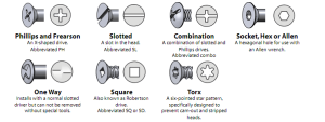
A Complete Guide on the Types Of Screw Head
You’ve probably stood in front of a confusing display of