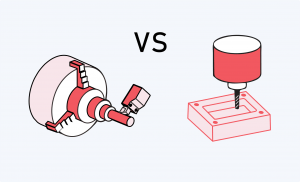
CNC Milling vs CNC Turning: Key Differences and How to Choose
Share: Table of Content Table of Content CNC milling and
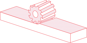
Plain Milling: Process, Applications, and Advantages
Share: Table of Content When I need to machine a
Share: Table of Content Table of Content CNC milling and
Share: Table of Content When I need to machine a